


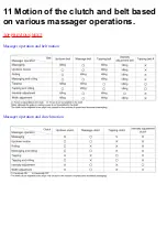


12 Massager up/down detection gear
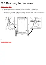
adjustment method
When the massager is removed from the chair, the position of the up/down detection gear changes,
resulting in a change of the up/down stop position.
When installing the massager on the back frame, be sure to adjust the position with the up/down
detection gear.
• Up/down detection gear position adjustment procedure
To make an adjustment, refer to the massager removing method (the back frame is tilted from the
chair).
1. Before mounting, the massager on the back frame must be moved down to the lowest position
by setting the controller manual operation UP/DOWN button to DOWN.
2. Mount the massager on the lowest position of the back frame.
3. Turn the hex nut M6 counterclockwise and move the massager upward.
4. Make sure that the massager has been mounted horizontally by moving the massager to the
position shown in the Figure.
*Unless the massager has been mounted horizontally, an abnormal sound or problem may
occur.
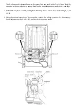
5. Move it up to the highest position(until the massager stops) by setting the controller manual
operation UP/DOWN button to UP.
6. Peeping into the square hole of the back frame, check the position of the massager to adjust.
*One thread of the up/down detection gear gives a stroke change of 4mm.
When the massager has been raised excessively : Turn the up/down detection gear clockwise to
adjust.
When the massager has been lowered excessively : Turn the up/down detection gear
counterclockwise to adjust.
Summary of Contents for EP790-C1
Page 2: ... TOP NEXT ...
Page 4: ... TOP PREVIOUS NEXT ...
Page 8: ... TOP PREVIOUS NEXT ...
Page 10: ... TOP PREVIOUS NEXT ...
Page 15: ...4 1 PARTS IDENTIFICATION TOP PREVIOUS NEXT TOP PREVIOUS NEXT ...
Page 16: ...4 2 TURNING ON THE POWER TOP PREVIOUS NEXT ...
Page 17: ...TOP PREVIOUS NEXT ...
Page 18: ...5 Required tools TOP PREVIOUS NEXT ...
Page 19: ...TOP PREVIOUS NEXT ...
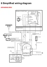
Page 20: ...6 Simplified wiring diagram TOP PREVIOUS NEXT ...
Page 21: ... TOP PREVIOUS NEXT ...
Page 26: ......
Page 32: ... TOP PREVIOUS NEXT ...
Page 35: ... TOP PREVIOUS NEXT ...
Page 39: ... ...
Page 40: ...TOP PREVIOUS NEXT ...
Page 43: ... TOP PREVIOUS NEXT ...
Page 54: ...TOP PREVIOUS NEXT ...
Page 56: ......
Page 57: ... TOP PREVIOUS NEXT ...
Page 61: ...15 7 Assembling TOP PREVIOUS NEXT 15 7 1 Assembling the oval gear TOP PREVIOUS NEXT ...
Page 63: ... TOP PREVIOUS NEXT ...
Page 65: ... TOP PREVIOUS NEXT ...
Page 67: ... TOP PREVIOUS NEXT ...
Page 71: ...TOP PREVIOUS NEXT ...
Page 73: ... TOP PREVIOUS NEXT ...
Page 74: ...16 Arranging massage block lead wires TOP PREVIOUS NEXT ...
Page 75: ...TOP PREVIOUS NEXT ...
Page 76: ...17 Actual wiring diagram TOP PREVIOUS NEXT ...
Page 77: ... TOP PREVIOUS NEXT ...
Page 78: ...18 Trouble shooting TOP PREVIOUS NEXT ...
Page 79: ......
Page 80: ......
Page 81: ......
Page 82: ... TOP PREVIOUS NEXT ...
Page 86: ...19 3 Q A TOP PREVIOUS NEXT TOP PREVIOUS NEXT ...
Page 88: ...20 EXPLODED VIEW TOP PREVIOUS NEXT TOP PREVIOUS NEXT ...
Page 95: ......
Page 96: ......


