


– 5-3 –
5.1.3. Functional Description
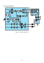
5.1.4. Transmitter
■
Introduction
This section provides a technical description of the transmitter circuits of the Main PCB. A circuit diagram of the whole system is
provided in the Service Manual.
■
Frequency Plan
The frequency plan is shown below:
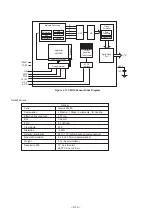
Figure 5.2. Synthesizer Block Diagram
TX Frequency
TX IF
TX UHF LO
E-GSM 900
880 MHz - 915 MHz
98.3 MHz - 114.4 MHz
1474.3 MHz -1543.8 MHz
GSM 1800
1710 MHz - 1785 MHz
90.3 MHz - 104.8 MHz
1354.7 MHz - 1414.5 MHz
GSM 850
824 MHz - 849 MHz
82.42 MHz - 105.55 MHz
1359.93 MHz - 1424.922 MHz
GSM 1900
1850 MHz - 1910 MHz
97.37 MHz - 112.34 MHz
1460.68 MHz - 1516.606 MHz
RX
RX LO
E-GSM 900
925 MHz - 960 MHz
925.2 MHz -959.8 MHz
GSM 1800
1805 MHz - 1880 MHz
1805.2 MHz - 1879.8 MHz
GSM 850
869 MHz - 894 MHz
869.2 MHz - 839.8 MHz
GSM 1900
1930 MHz - 1990 MHz
1930.2 MHz - 1989.8 MHz
PFD
PFD
R div.
M div.
26 MHz
I
Q
MAIN PLL
TX LB VCO
= TX GSM850 / GSM900
TX HB VCO
= TX GSM1800 / GSM1900
toward PA
PAD
L
divider
N divider
MAIN VCO 2
@3.80 GHz
MAIN VCO 1
@3.37 GHz
Programmable
Main loop filter
90
°
toward RX mixers
Summary of Contents for EB-X100
Page 68: ... 8 19 ...
Page 69: ... 8 20 ...