


6
2
Overview and Controls
This section provides information about front panel and rear panel. When you install this
series DVR for the first time, please refer to this part first.
2.1
Front Panel
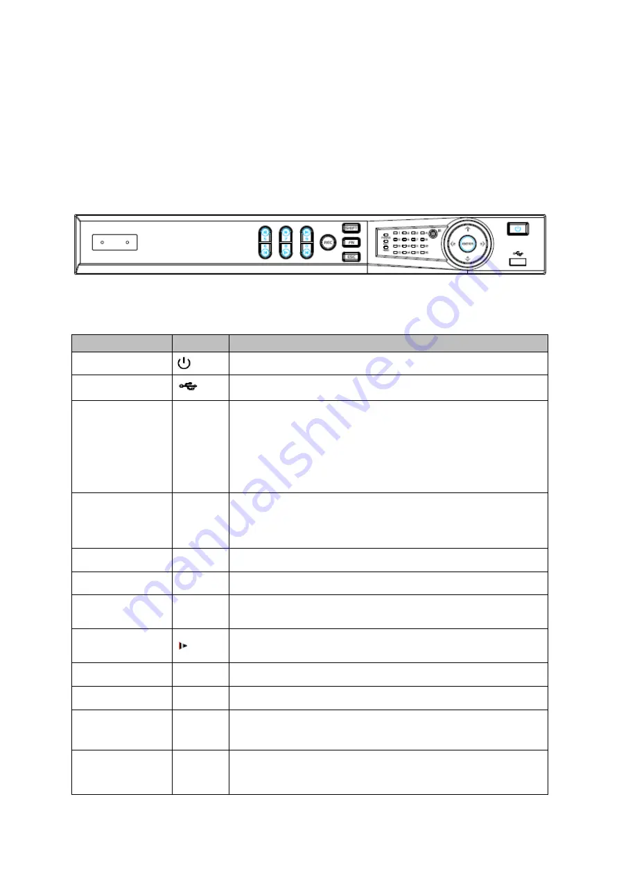
2.1.1 CJ-HDR216
The front panel is shown as below. See Figure 2-1.
Figure
2-1
Please refer to the following sheet for front panel button information.
Name
Icon
Function
Power button
Press this button to boot up or shut down the device.
USB port
Connect to USB2.0 storage device, mouse and etc.
Up/1
Down/4
/
Activate current controls, and then move up, move down or
jump.
Change setup, increase/decrease numeral.
Assistant function such as PTZ menu.
Switch channel when playback.
Left/2
Right/3
/
Switch current activated controls, move up and down.
When device is in 1-channel playback mode, use it to control
playback control bar process.
Play/Pause/5
When playback, click it to pause, click it again to play again.
Reverse/Pause/6
When playback, click it to begin reverse play.
Fast forward/7
When playback, it supports various fast forward speeds and
normal playback.
Slow playback/8
When playback, it supports various slow playback speeds and
normal playback.
Play Next /9
│
When playback, click it to view the next record.
Play previous/0
│
When playback, click it to view the previous record.
Record indicator
1
~
16
It is to display system is recording or not
The light becomes on when system is recording.
Cancel
ESC
Go to previous menu, or cancel current operation (Close the
top interface or controls).
When playback, click it to restore real-time monitor mode.
Summary of Contents for CJ-HDR216
Page 1: ...HD Analog Recorder User s Manual Model No CJ HDR216 CJ HDR416 Version 1 0 3 ...
Page 93: ...85 Figure 4 72 Figure 4 73 ...
Page 94: ...86 Figure 4 74 Figure 4 75 ...
Page 99: ...91 Figure 4 79 Figure 4 80 ...
Page 102: ...94 Figure 4 84 Figure 4 85 ...
Page 108: ...100 Figure 4 93 Figure 4 94 ...
Page 110: ...102 Figure 4 96 Figure 4 97 ...
Page 116: ...108 Figure 4 104 Figure 4 105 ...
Page 120: ...112 Figure 4 109 Figure 4 110 ...
Page 130: ...122 Figure 4 120 Figure 4 121 ...
Page 164: ...156 Figure 5 46 Figure 5 47 ...
Page 168: ...160 Figure 5 51 Figure 5 52 Please refer to the following sheet for detailed information ...
Page 172: ...164 Blue color stands for MD alarm record snapshot Figure 5 56 Figure 5 57 ...


