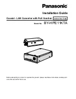
Installation Guide
Coaxial - LAN Converter with PoE function
Indoor Use Only
Model No.
BY-HPE11KTA
Before attempting to connect or operate this product, please read these instructions carefully andsave this manual for future use.
Page 1: ... Guide Coaxial LAN Converter with PoE function Indoor Use Only Model No BY HPE11KTA Before attempting to connect or operate this product please read these instructions carefully and save this manual for future use ...
Page 2: ...ss security products coax index html For U S A The KT serial number of this product may be found on the surface of the unit You should note the model number and KT serial number of this unit in the space provided and retain this book as a permanent record of your purchase to aid identification in the event of theft Model No KT Serial No RG 6 U coaxial cable In this document coaxial cables with the...
Page 3: ...nd 2 km 6 561 feet 8 inches for non PoE connections When used with RG 6 U coaxial cable High speed transmission The coaxial LAN converter is capable of transmission speeds of 35 Mbps or over for TCP 2 and 45 Mbps or over for UDP connections When used with RG 6 U coaxial cable and for distances under 2 km 6 561 feet 8 inches No setup required Connections can be established by simply connecting the ...
Page 4: ...ective owners About copyright and license Distributing copying disassembling reverse compiling reverse engineering and also exporting in violation of export laws of the software provided with this unit are expressly prohibited Limitation of liability THIS PUBLICATION IS PROVIDED AS IS WITHOUT WARRANTY OF ANY KIND EITHER EXPRESS OR IMPLIED INCLUDING BUT NOT LIMITED TO THE IMPLIED WARRANTIES OF MERC...
Page 5: ...ur responsibility to take precautions such as those described below to protect yourself against the above network security risks Use this unit in a network secured by a firewall etc If this unit is connected to a network that includes PCs make sure that the system is not infected by computer viruses or other malicious entities using a regularly updated anti virus program anti spyware program etc P...
Page 6: ... a firewall feature To prevent unauthorized external access to the network we recommend performing the following procedures Setup security measures for the router and computers accessing the network Change the default password on the adaptor s maintenance screen see 3 2 3 Changing Adaptor Settings Changing the adaptor s password in the Operating Instructions on the CD ROM 6 Installation Guide Othe...
Page 7: ...ion Guide this document 1 pc Warranty Card 1 1 pc CD ROM 2 1 pc AC Cord 1 pc Safety Wire 1 pc BNC Connector Cover 2 pcs Screw 3 pcs For the safety wire and BNC connector covers 1 For U S A only 2 Contains the documentation including the Operating Instructions Installation Guide 7 Included Items ...
Page 8: ...rized service center for repairs Do not disassemble or repair the unit To reduce the risk of electric shock or fire do not disassemble the unit Contact an authorized service center when service is required Use only the power source specified for the unit Overloading the unit by having many loads on one electrical outlet etc may cause excessive heat resulting in fire Completely insert the power plu...
Page 9: ... fall causing serious damage and or injury Consult an authorized dealer for checks Mount the unit to secure locations that can support the weight of the unit Serious damage and or injury may result if the unit falls Reinforce the mounting area if it has insufficient strength to secure the unit Make sure to use the safety wire Attach the safety wire in a position so that if the camera adaptor were ...
Page 10: ...rom the unit may affect the operation of medical equipment and cause malfunctions Do not expose the unit to rain or any type of moisture To prevent the risk of fire or electrical shock do not place objects such as cups or vases near the unit If the unit is exposed to moisture disconnect the AC cord and contact an authorized service center Do not touch the core of the coaxial cable A maximum of DC ...
Page 11: ...This may damage the cables or connectors and result in electric shock Do not connect other devices to the BNC connector of the unit This may damage the unit Do not expose the unit to fire or naked flames This may result in fire The AC cord is used as the main disconnect device Ensure that the power outlet is installed near the unit and is easily accessible Do not play the included CD ROM in an aud...
Page 12: ...r a bathtub washbowl kitchen sink or laundry tub in a wet basement or near a swimming pool 2 Avoid handling or installing the unit connecting wiring or touching the AC cord power plug LAN cable or coaxial cable during an electrical storm 3 Do not use the unit in the vicinity of a gas leak 4 Use only the AC cord indicated in this manual SAVE THESE INSTRUCTIONS 12 Installation Guide Important Safety...
Page 13: ...nce to radio communications Operation of this equipment in a residential area is likely to cause harmful interference in which case the user will be required to correct the interference at his own expense This device complies with part 15 of the FCC Rules Operation is subject to the following two conditions 1 This device may not cause harmful interference and 2 this device must accept any interfer...
Page 14: ... not use the unit in areas with high temperatures or humidity for long periods of time Use in these areas can degrade parts which can shorten the life span of the unit We recommend areas that have temperatures of 35 C 95 F or lower Do not install the unit in places that can be directly exposed to heat sources 5 Proper handling of the unit Do not drop or expose the unit to strong vibrations or shak...
Page 15: ...s from the sea where the temperature or humidity exceeds the operating environment specifications for the unit Camera Adaptor BY HPE11R Temperature 10 C 14 F to 50 C 122 F Humidity 20 90 Center Adaptor BY HPE11H Temperature 0 C 32 F to 50 C 122 F Humidity 20 85 where the unit can be exposed to vibrations such as in cars or boats the unit is not designed to be installed in vehicles where the unit c...
Page 16: ...e screws that are appropriate for the material of the ceiling wall or rack Do not use impact drills Impact drills may damage the screws Secure screws in a straight line into the ceiling wall or rack Confirm that screws are flush with the surface that they are secured to 6 Using the safety wire Attach the safety wire in a position so that if the camera adaptor were to become detached it would not f...
Page 17: ...r provided Tip dimensions inside the recommended BNC plug Diameter 1 32 mm 0 052 inches to 1 37 mm 0 054 inches Diameter 0 13 mm 0 005 inches to 0 69 mm 0 027 inches IMPORTANT Use a suitable plug Using a non specified plug may cause a bad connection or cause damage to the BNC connector 8 Mounting and connections Do not mount camera adaptors above or below other camera adaptors This can cause trans...
Page 18: ...ter Adaptor BY HPE11H 21 1 3 Understanding the Indicators 22 2 Mounting the Unit 23 2 1 Mounting the Camera Adaptor 23 2 2 Mounting the Center Adaptor to a Rack 25 3 Connecting the Unit 28 3 1 Connection Example 28 3 2 Connections 29 18 Installation Guide Table of Contents ...
Page 19: ...ring the network camera with an AC adaptor set it to OFF The PoE function cannot be used for connections over 500 m 1 640 feet 5 inches Set the PoE switch to OFF C BNC connector Connects the camera adaptor to the center adaptor with a coaxial cable see page 30 D Network connector Connects the camera adaptor to a network camera with a LAN cable see page 29 E INITIAL SET button Used to reset the cam...
Page 20: ...attaching the camera adaptor to a ceiling or wall with screws see page 24 B Used when attaching the safety wire see page 23 C Used when attaching the camera adaptor to screws inserted into a wall 20 Installation Guide 1 Main Unit ...
Page 21: ...o its factory default settings see 2 2 Resetting Center Adaptors in the Operating Instructions on the CD ROM D Network connector Connects the center adaptor to a network device with a LAN cable see page 32 Rear view A B A BNC connector Connects the center adaptor to the camera adaptor with a coaxial cable see page 31 B AC IN Connects the center adaptor to the power outlet with the included AC cord...
Page 22: ... The center adaptor may be connected to a device other than the camera adaptor with the coaxial cable Check the connection with the camera adaptor Off The center adaptor is not connected to the power outlet LAN Green lit A network device is connected Green flashing Sending receiving data from a network device Orange lit A network device is not connected or the connected network device is not conne...
Page 23: ...e adaptor from falling Consult an authorized dealer for mounting Do not mount camera adaptors above or below other camera adaptors This can cause transmission interference When mounting several camera adaptors in the same area mount them side by side each other The pull out strength of the installation area must be at least 294 N 30 kgf per screw 1 Secure the safety wire to the camera adaptor with...
Page 24: ...3 16 inches 3 Secure the safety wire to the ceiling or wall using a screw customer provided length 20 mm 13 16 inches body diameter 4 mm 3 16 inches Use screws that are appropriate for the material of the ceiling or wall Attach the safety wire in a position so that if the camera adaptor were to become detached it would not fall on nearby people Screw customer provided length 20 mm 13 16 inches bod...
Page 25: ...cs Screw M3 6 6 pcs IMPORTANT Make sure to use the screws included with the BY HCA10A Mounting 3 or 4 center adaptors to a rack 1 Connect the center adaptors together using the BY HCA10A underside continuous connecting brackets with the screws included with the BY HCA10A Connecting 3 center adaptors Place a center adaptor on both ends of the underside continuous connecting brackets Recommended tor...
Page 26: ...derside continuous connecting bracket 2 Secure the BY HCA10A mounting brackets to both sides of the connected center adaptors with the screws included with the BY HCA10A Recommended torque 0 4 1 0 N m 4 1 10 2 kgf cm Mounting bracket Mounting bracket Screw M3x6 6 pcs 26 Installation Guide 2 Mounting the Unit ...
Page 27: ... a fan or other device to keep the temperature in the rack under 30 C 86 F Rack mounting screw customer provided nominal diameter 5 mm 3 16 inches tapping IMPORTANT Take measures to ensure that the temperature in the rack does not exceed 45 C 113 F When mounting center adaptors to the rack leave 1U 44 mm 1 3 4 inches or more clearance above and below the adaptors Installation Guide 27 2 Mounting t...
Page 28: ...her cable for the LAN cable When using PoE to supply power to the network camera from the camera adaptor we recommend using 100 W balanced LAN cable that complies to the ISO IEC 11801 2002 IEEE802 3af Annex 33B IMPORTANT Use all 4 pairs 8 pins of the LAN cable The maximum length of LAN cable that can be used is 100 m 328 feet 1 inch When reconnecting the LAN cable wait for at least 2 seconds after...
Page 29: ...xial cable are customer provided IMPORTANT Connect the center adaptor to the power outlet only after completing all the connections 1 Connect a LAN cable Cat 5e or higher to the camera adaptor and network camera Network camera LAN cable Network connector Network connector PoE switch IMPORTANT Turn the PoE switch to ON when using the PoE function to supply power to a network camera When using an AC...
Page 30: ... may cause damage to the connected device When using existing coaxial cables disconnect other devices that are connected to the coaxial cable before connecting to the unit Measure the insulation resistance of the coaxial cable new or existing before making connections Insulation resistance value 1 MW or more for DC 500 V Confirm the length of the coaxial cable when using the PoE function The maxim...
Page 31: ... First pass the coaxial cable through the included BNC connector cover then connect the coaxial cable to the BNC connector of the center adaptor Never touch the core Connect to the camera adaptor Do not connect to another device BNC connector Coaxial cable When using an existing cable you must disconnect it from another device before connecting BNC connector cover Installation Guide 31 3 Connectin...
Page 32: ...rk device LAN cable Network connector Network connector Network device 7 Connect the AC cord to the AC IN jack of the center adaptor then plug the AC cord into the power outlet AC cord included To the power outlet AC IN When you operate the center adaptor the power outlet should be near the center adaptor and easily accessible To prevent the AC cord from being disconnected if it is pulled do not p...
Page 33: ...s SPEED button for about 1 second POWER LAN COAXIAL SPEED button The transmission speed between the camera adaptor and center adaptor will be measured During measurements the indicators of the center adaptor will be lit in the following order POWER LAN COAXIAL POWER LAN COAXIAL POWER LAN COAXIAL Green Green Green Installation Guide 33 3 Connecting the Unit ...
Page 34: ...10 Confirm that all 3 of the center adaptor s indicators are lit for about 6 seconds POWER LAN COAXIAL Green Green Green 34 Installation Guide 3 Connecting the Unit ...
Page 35: ...Installation Guide 35 Notes ...
Page 36: ...support call 1 800 528 6747 Three Panasonic Way Secaucus New Jersey 07094 U S A 5770 Ambler Drive Mississauga Ontario L4W 2T3 Canada 905 624 5010 www panasonic ca Panasonic System Networks Co Ltd 2010 Printed in Malaysia PNQX3079ZA KK1110MJ0 ...