


DVQP2261ZA
W0820RA0 -FJ
ENGLISH
Model No.
AW‑UE100WP
Model No.
AW‑UE100KP
Model No.
AW‑UE100WPC
Model No.
AW‑UE100KPC
Model No.
AW‑UE100WE
Model No.
AW‑UE100KE
Model No.
AW‑UE100WED
Model No.
AW‑UE100KED
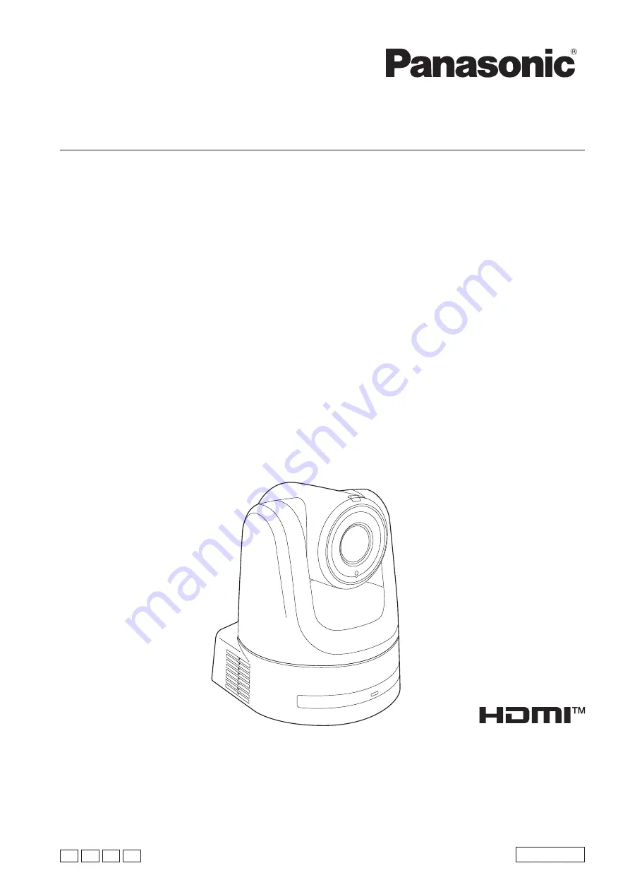
Operating Instructions
4K Integrated Camera
Before operating this product, please read the instructions carefully and save this manual for future use.
Please carefully read the “Read this first!” (pages 2 to 7) of this Manual before use.
PJ PC EJ ED


