background image


This document is described functions of AW-RP150 SYSTEM VERSION Ver 2.00-00-0.09. Please 
see also the operating instructions of ROPs. 
 

No.3 

A ROP setting menu is added so that the selected camera at the AW-RP150 

can be activated on the connected ROP.   
  

-

 AK-HRP1000/AK-HRP1005 ver.4.80-00-0.03 or higher 


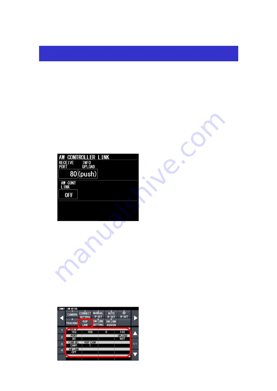
To use the ROP linkage function, PORT number of RP150 has to be same as one of ROP. 

Setting ROP


MENU

】>

AW CONTROLLER LINK   

Set up the PORT No. for RP150 to “RECEIVE PORT” and execute “INFO UPLOAD”. 
Set  “AW CONT LINK”  to ON. 


Setting RP150


MENU

  SYSTEM 

  ROP LINK 

Set up “ROP IP” and “PORT” for ROP.    And execute “UPLOAD”. 
Assign “CAMSEL” for RP150 and “ROP CAM” for ROP. 
 
Target CAM No. can be set at “ROP CAM” against CAMSEL in RP150. 
    Initial setting : CAM1 –CAM99 is 1 – 99 
                          CAM100 - CAM200 is NON 
    In case of no assigned CAMERA, please set it “NON”. 

 
When “AW LINK” is turned on, RP150 starts to communicate to ROP. 


Operating guide for AW-RP150 Ver2 

Summary of Contents for AW-RP150

Page 1: ...50 has to be same as one of ROP Setting ROP MENU AW CONTROLLER LINK Set up the PORT No for RP150 to RECEIVE PORT and execute INFO UPLOAD Set AW CONT LINK to ON Setting RP150 MENU SYSTEM ROP LINK Set up ROP IP and PORT for ROP And execute UPLOAD Assign CAMSEL for RP150 and ROP CAM for ROP Target CAM No can be set at ROP CAM against CAMSEL in RP150 Initial setting CAM1 CAM99 is 1 99 CAM100 CAM200 is...

Page 2: ... S F ME2KEY2 S F ME2KEY3 S F ME2KEY4 S F DSK1 S K DSK2 S K DSK3 S K DSK4 S K FOCUS ASSIST FASIST ON Switch to assigned Remote Camera OFF MV1 AUX Bus output from HS6000 switch to MV1 OFF MV2 AUX Bus output from HS6000 switch to MV2 OFF MV3 AUX Bus output from HS6000 switch to MV3 OFF MV4 AUX Bus output from HS6000 switch to MV4 When RP150 is turned on it indicates MV1 4 OUTBUS MV1 4 OFF AUX1 AUX16 ...

Page 3: ...1 200 CAM No can be assigned against SW INPUT 1 34 No 5 All Delete function of TMEM Tracing Memory is added Delete function all TMEM data on the target camera MENU PMEM TMEM TMEM MODE DEL ALL No 6 Camera Group number indication is added under the Status display ...

Page 4: ...ton MENU FUNCTION CAMERA_INFO I ZOOM ON OFF When camera supports I ZOOM function it can be turned on off From RP150 MENU FUNCTION USER ASSIGN USER1 10 I ZOOM You can assign to User button No 9 A CAMSEL OP menu is added Usually camera selection is not possible during operation PAN TILT ZOOM When this menu is set to MULTI you can select another camera even during operation MENU MAINTENANCE RP SETTIN...

Page 5: ...ME EDIT PMEM1 PMEM100 F1 for enter one character F2 for delete on character NOTE Store and Delete button of PMEM will be disappeared when PMEM List is displayed In this case move to other menu setting and come back No 12 One of 7 colors is assignable to Each PRESET button You can change Button color if PRESET is registered 7 colors MENU PMEM TMEM VIEW COLOR F1 F4 dial select color You can save the...

Page 6: ... Each direction of PAN TILT Zoom Focus Iris is according to direction information on each camera Note Direction information on each camera can be stored loaded into SD card MAINTE RP SETTING CAMINF SV CAMINF LD No 15 PRESET LIST display is added on Status screen PRESET information can be displayed with Lens information Status Screen Camera GAIN PED Camera USER buttons Camera Preset Memory LIST ...

Reviews: