background image

AV4 (FU) Miniature Switches

Panasonic Corporation Electromechanical Control Business Division

industrial.panasonic.com/ac/e/

 2 

© Panasonic Corporation 2019

AECTB16E  201903

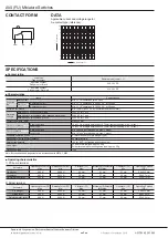
CONTACT FORM

SPECIFICATIONS

■ Contact rating

■ Characteristics

■ Operating characteristics

DATA

Applicable current and voltage range for

Au contact type (reference)

100

200

50

10

1

0.2
0.1

5

12

24

30

DC voltage (V)

Current (mA)

Load type

Type of contact

Resistive load (cosφ

1)

Ag plated contact 

Plunger color: Black

0.5A 30V DC

Au plated contact 

Plunger color: Dark red

0.1A 30V DC

Items

Specifications

Expected 

life

Mechanical

Min. 3 × 10

operations (at 60 cpm)

Electrical

Ag plated contact

Min. 2 × 10

operations (0.5A 30V DC; at 20 cpm)

Au plated contact

Min. 2 × 10

operations (0.1A 30V DC; at 20 cpm)

Insulation resistance

Min. 100 MΩ (250V DC by insulation resistance meter)

Dielectric 

strength

Between non-continuous terminals

500V AC for 1 min.

Between each terminal and other exposed metal parts

500V AC for 1 min.

Between each terminal and ground

500V AC for 1 min.

Contact resistance (initial)

Max. 200 mΩ

Vibration resistance

Pin plunger type

10 to 55 Hz at single amplitude of 0.75mm (contact opening: max. 1 msec.)

Lever type

10 to 55 Hz at single amplitude of 0.15mm (contact opening: max. 1 msec.)

Shock resistance

Pin plunger type

Min. 294m/s

(contact opening: max. 1 msec.)

Lever type

Min. 147m/s

(contact opening: max. 1 msec.)

Allowable operation speed

0.1mm/s to 500mm/s (pin plunger type)

Mechanical max. switching frequency

60 operations/min.

Ambient temperature

–25 to +80°C (no freezing and condensing)

Unit weight

PC board terminal type: Approx. 0.2g

Solder terminal with mounting holes type: Approx. 0.3g

Protection grade

IP40

Note: Test conditions and judgement are in accordance with NECA C 4505.

1) PC board terminal

Actuators

Operating Force (OF) 

Max.

Release Force (RF) 

Min.

Pretravel (PT) 

Max.

Movement Differential 

(MD) Max.

Overtravel (OT) 

Min.

Operating Position 

(OP)

Pin plunger

0.98 N

0.098 N

0.3 mm

0.1 mm

0.1 mm

4.8±0.15 mm

Hinge lever

0.25 N

0.010 N

2.4 mm

0.7 mm

0.4 mm

5.8±0.7 mm

Simulated roller lever

0.29 N

0.010 N

2.2 mm

0.7 mm

0.3 mm

6.1±0.7 mm

2) Solder terminal

Actuators

Operating Force (OF) 

Max.

Release Force (RF) 

Min.

Pretravel (PT) 

Max.

Movement Differential 

(MD) Max.

Overtravel (OT) 

Min.

Operating Position 

(OP)

Pin plunger

0.98 N

0.098 N

0.3 mm

0.1 mm

0.1 mm

5.4±0.15 mm

Hinge lever

0.25 N

0.020 N

2.4 mm

0.7 mm

0.4 mm

6.4±0.6 mm

Simulated roller lever

0.29 N

0.020 N

2.2 mm

0.7 mm

0.3 mm

6.7±0.5 mm

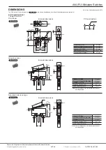
COM

NC

NO

Summary of Contents for AV4

Page 1: ...ever 4 Simulated roller lever Contact material Nil Ag plated contact 61 Au plated contact Terminals 0 Solder terminal with mounting holes 1 65 mm dia 4 PC board straight terminal 5 PC board angle terminal Right angle terminal 6 PC board reverse angle terminal Left angle terminal Operating Force OF max by pin plunger 4 0 98 N Type of contacts Actuator Operating Force OF Max Part No PC board termina...

Page 2: ...ude of 0 75mm contact opening max 1 msec Lever type 10 to 55 Hz at single amplitude of 0 15mm contact opening max 1 msec Shock resistance Pin plunger type Min 294m s2 contact opening max 1 msec Lever type Min 147m s2 contact opening max 1 msec Allowable operation speed 0 1mm s to 500mm s pin plunger type Mechanical max switching frequency 60 operations min Ambient temperature 25 to 80 C no freezin...

Page 3: ... 08 0 02 3 1 0 dia Pretravel PT Max 0 3 mm Movement Differential MD Max 0 1 mm Overtravel OT Min 0 1 mm Operating Position OP 4 8 0 15 mm Free Position FP Max 5 2 mm 3 95 2 4 Max 3 0 6 5 5 8 7 5 Max FP OP PT 1 7 0 6 0 55 0 55 0 11 0 8 2 5 2 5 0 7 0 7 Note All other dimensions are the same as those of pin plunger type CAD Data Simulated roller lever type External dimensions 6 1 0 7 5 5 2 2 Max 0 6 ...

Page 4: ...sions Pretravel PT Max 0 3 mm Movement Differential MD Max 0 1 mm Overtravel OT Min 0 1 mm Operating Position OP 4 8 0 15 mm Free Position FP Max 5 2 mm Note All other dimensions of hinge lever type and simulated roller lever type are the same as those of straight terminal types Pin plunger Pin plunger Left angle terminal 3 1 2 4 0 7 0 6 0 5 1 7 0 55 0 55 0 11 0 8 2 5 0 5 0 8 1 9 0 8 1 0 0 6 0 6 5...

Page 5: ... more than 0 098 N m 2 In setting the movement after operation the over travel should be set within the range of the minimum OT value Please set up so that a operation object does not apply force to the switch body Environment Avoid using and storing these switches in a location where they will be exposed to corrosive gases silicon or high dust levels all of which can have an adverse effect on the...

Page 6: ...e rated load is connected to the contact and switching operations are performed The life test is performed at a switching frequency of 20 times minute and operating speed of 100 mm second at the regular cam Contact form This refers to the components determining the type of application which make up the electrical input output circuits in the contact Insulation resistance Resistance between non con...

Page 7: ... stroke setting is the key to high reliability It is also important that adequate contact force be maintained to ensure high reliability For a normally closed NC circuit the driving mechanism should be set so that the actuator is normally in the free position For a normally open NO circuit the actuator should be pressed to 70 to 100 of the specified stroke to absorb possible errors If the stroke i...

Page 8: ...el load type Contact resistance across COM and NC terminals is measured in the free position while contact resistance across COM and NO terminals is measured in the total travel position 7 To prevent contact welding failure be sure to use a serial resistance for each capacitive load 8 If snap action switch operation is synchronized with the AC supply phase this may cause shortened electrical life ...

Page 9: ...al portions immediately after soldering The temperature setting and time conditions vary depending on the product See the section CAUTIONS FOR USE for each product Avoid using in a silicon atmosphere Avoid using organic silicon rubber adhesives sealing compounds oil grease and wires in a silicon atmosphere Please consult us when using under the following conditions 1 Environments where hydrogen su...

Page 10: ...ational time lags The plastic becomes brittle if the switch is exposed to a low temperature low humidity environment for long periods of time Storage for extended periods of time including transportation periods at high temperatures or high humidity levels or in atmospheres with organic gases or sulfide gases may cause a sulfide film or oxide film to form on the surfaces of the contacts and or it ...

Page 11: ... force required for operation Appropriate for use with low speed cams and dogs has large stroke Lever available in various shapes to fit operating unit Simulated roller lever Large Medium Small Possible Tip of hinge lever is bent into a semi circle enabling use as a simple roller type Leaf lever Large Large Small Excellent Play in lever is used to assure maximum stroke Construction provides for sp...

Page 12: ...2019 AECTB16E 1 201903 ...

Page 13: ...Mouser Electronics Authorized Distributor Click to View Pricing Inventory Delivery Lifecycle Information Panasonic AV402461 ...

Reviews: