background image

– 62 –

Chapter 4 Shooting — Adjusting image quality


r

Advanced settings

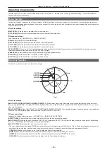
Configure the settings in the main menu 

 [SCENE FILE] 

 [KNEE SETTING].

[KNEE MODE]:

 Sets the operation mode of knee function ([AUTO]/[MANUAL]/[OFF]).


f

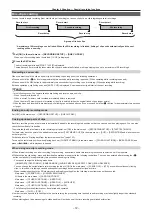
When [AUTO] is selected in [KNEE SETTING]

[A.KNEE RESPONSE]:

 Sets the speed of response. Smaller values make the response faster.


f

When [MANUAL] is selected in [KNEE SETTING]

[KNEE MASTER POINT]:

 Sets the knee point position in 0.5% steps.

[KNEE MASTER SLOPE]:

 Sets the knee inclination.

[KNEE MASTER SLOPE Rch]:

 Sets the knee inclination of Rch.

[KNEE MASTER SLOPE Bch]:

 Sets the knee inclination of Bch.

High color function

This function sets the color dynamic range.


r

General settings

[HI-COLOR SW]:

 Turns the mode that expands the color dynamic range [ON]/[OFF].

[HI-COLOR LVL]:

 Selects the level of mode that expands the color dynamic range.


r

Advanced settings

Use the camera in a general settings.

White clip function

This function sets the brightest part of video signals to be not brighter than a certain level.


r

General settings

Use the camera with the factory settings.


r

Advanced settings

Configure the settings in the main menu 

 [SCENE FILE] 

 [WHITE CLIP SETTING].

[WHITE CLIP]:

 Turns the white clip function [ON]/[OFF]. When the function is [ON], the setting value of [WHITE CLIP LVL] is enabled.

[WHITE CLIP LVL]:

 Sets the white clip level.

[Rch CLIP LVL]:

 Sets the clip level of Rch for white clips.

[Bch CLIP LVL]:

 Sets the clip level of Bch for white clips.

Summary of Contents for AJ-PX230 Series

Page 1: ...rder Before operating this product please read the instructions carefully and save this manual for future use Before using this product be sure to read Read this first pages 2 to 8 ENGLISH VQT5M55A E W0316HM0 YI Model No AJ PX230 Model No AJ PX230E ...

Page 2: ...damage the unit or result in personal injury CAUTION The mains plug of the power supply cord shall remain readily operable The AC receptacle mains socket outlet shall be installed near the equipment and shall be easily accessible To completely disconnect this equipment from the AC mains disconnect the power cord plug from the AC receptacle CAUTION Danger of explosion or fire if battery is incorrec...

Page 3: ... a bateria Battery release button Botão de liberação da bateria Back up Battery Lithium Battery For the removal of the battery for disposal at the end of its service life please consult your dealer r r Batteries that may be used with this product Correct as of March 2016 Panasonic VW VBD58 batteries may be used with this product It has been found that counterfeit battery packs which look very simi...

Page 4: ...lf Declaration Conforming to IS 616 2010 R 41016268 VSK0726 IS 616 2010 R 41023167 DE A88D IS 16046 2012 R 41022500 VW VBD58 Декларація про Відповідність Вимогам Технічного Регламенту Обмеження Використання деяких Небезпечних Речовин в електричному та електронному обладнанні затвердженого Постановою 1057 Кабінету Міністрів України Виріб відповідає вимогам Технічного Регламенту Обмеження Використан...

Page 5: ...These limits are designed to provide reasonable protection against harmful interference in a residential installation This equipment generates uses and can radiate radio frequency energy and if not installed and used in accordance with the instructions may cause harmful interference to radio communications However there is no guarantee that interference will not occur in a particular installation ...

Page 6: ...tlet 10 Protect the power cord from being walked on or pinched particularly at plugs convenience receptacles and the point where they exit from the apparatus 11 Only use attachments accessories specified by the manufacturer 12 Use only with the cart stand tripod bracket or table specified by the manufacturer or sold with the apparatus When a cart is used use caution when moving the cart apparatus ...

Page 7: ... please ensure that the replacement fuse has a rating of 5 amps and that it is approved by ASTA or BSI to BS1362 Check for the ASTA mark or the BSI mark on the body of the fuse If the plug contains a removable fuse cover you must ensure that it is refitted when the fuse is replaced If you lose the fuse cover the plug must not be used until a replacement cover is obtained A replacement fuse cover c...

Page 8: ...taken to resume from Stand by mode Manufactured by Panasonic Corporation Osaka Japan Importer s name and address of pursuant to EU rules Panasonic Marketing Europe GmbH Panasonic Testing Centre Winsbergring 11 22525 Hamburg Germany EU Disposal of Old Equipment and Batteries Only for European Union and countries with recycling systems These symbols on the products packaging and or accompanying docu...

Page 9: ...elow To record video in compliance with the AVC standard AVC Video To play back AVC Video that was recorded by a consumer engaged in a personal and non commercial activity To play back AVC Video that was obtained from a video provider licensed to provide the video Visit the MPEG LA LLC website http www mpegla com for details f f Use of DCF Technologies under license from Multi Format Inc How to re...

Page 10: ...Setting the ZOOM switch 58 Adjusting the zoom position 58 Zoom ring 58 Adjusting image quality 59 Detail function 59 Skin tone function 59 RB gain control function 60 Chroma setting function 60 Matrix function 60 Color correction function 61 Black control function 61 Gamma function 61 Knee function 61 High color function 62 White clip function 62 Setting the electronic shutter 63 Shutter mode 63 A...

Page 11: ...DIO SETUP 133 OUTPUT SEL 134 USB SETUP 135 DISPLAY SETUP 135 CARD FUNCTIONS 138 OTHER FUNCTIONS 138 MAINTENANCE 138 DIAGNOSTIC 139 USER MENU SEL 139 OPTION MENU list 140 AREA SELECT 140 AWB PRE CONTROL 140 CAM REMOTE ADJ 140 LCD SUB BRIGHTNESS 140 ENG SECURITY 140 Chapter 7 Display 141 Screen status display 142 Configuration of status display on screen 142 Selecting display items on screen 142 Dis...

Page 12: ...Before using the camera read this chapter Chapter 1 Overview ...

Page 13: ...perly f f If you carry the camera recorder use a grip strap or shoulder strap and handle it carefully r r Do not apply insecticide or volatile materials to the camera recorder f f If insecticide or volatile materials come into contact with the camera recorder the camera recorder body may warp and the paint may come off f f Do not allow the camera recorder to remain in contact with rubber or vinyl ...

Page 14: ...vent laser beams from striking the lens when shooting in an environment where laser devices are used r r Note the following points f f If you prepare to record important images always shoot some advance test footage to verify that both pictures and sound are being recorded normally f f Should video or audio recording fail due to a malfunction of the camera or the microP2 memory card during the use...

Page 15: ... initialized according to the region of use selected and automatically restarted After setting up the region of use once this screen will not be displayed when subsequently turning the power on To change the region of use set it in OPTION MENU AREA SETTING NOTE t t When making this setting to use the camera for the first time only the following items are changed on the camera Menu setting values o...

Page 16: ...For India 2 f f For areas except USA Canada and India 4 Shoulder strap page 31 Microphone holder page 33 12 mm screws for microphone holder 2 page 33 Eye cup page 32 Lens hood already attached to the product page 31 Grip belt already attached to the product page 31 NOTE t t Dispose the AC cable cap only if attached and packing material properly after unpacking the product ...

Page 17: ...stereo microphone phantom 48V AG MC200G Attaching the front microphone page 33 Battery VW VBD58 7 2 V 5800 mAh Product comparable to the included battery CGA D54 CGA D54s 7 2 V 5400 mAh Attaching and removing the battery page 29 SD memory card microP2 memory card Visit the support desk at the website microP2 memory card page 38 For the latest information on microP2 memory card and SD memory card t...

Page 18: ...ording f f AVC Ultra system codec support f f Simultaneous recording f f Background recording f f Variable frame rate Slow quick motion recording SD memory card Settings for user files and scene files etc can be stored in and loaded from the SD memory card Linking to external devices USB device mode Data files for performing nonlinear editing on a computer are transferred microP2 memory card 1 Per...

Page 19: ...This chapter describes the names functions and operations of parts on the camera Chapter 2 Description of Parts ...

Page 20: ... the brightness of the screen according to the lighting conditions under which you are shooting 8 F AUDIO LEVEL dial page 68 In the following conditions the recording levels for the audio channels 1 to 4 can be adjusted f f When the CH1 CH2 switch is set to MANU f f When AUTO LEVEL CH3 AUTO LEVEL CH4 is set to OFF in the main menu AUDIO SETUP RECORDING CH SETTING Assignment of audio channels 1 to ...

Page 21: ...w strong the lever is pushed When pushed gently the speed becomes slower and when pushed strongly it becomes faster OFF The zoom lever does not work 22 ND FILTER switch page 51 Select the filter to suit the illumination of the subject 1 64 Reduce the amount of light entering the MOS sensor to 1 64 1 16 Reduce the amount of light entering the MOS sensor to 1 16 1 4 Reduce the amount of light enteri...

Page 22: ...o av panasonic net SDHC memory cards are a standard that was established in 2006 by the SD Association for large capacity memory cards that exceed 2 GB SDXC memory cards are a standard that was established in 2009 by the SD Association for large capacity memory cards that exceed 32 GB 5 Recording button grip side page 48 Press this button to start recording Press it again to stop recording Used fo...

Page 23: ... 23 Chapter 2 Description of Parts Right side 15 USB2 0 HOST terminal sub host This is the USB terminal for maintenance ...

Page 24: ... hold the camera or by hitting the strong light around the eye piece 7 Viewfinder page 45 8 AUDIO INPUT 1 terminal XLR 3 pin page 33 Connect the audio equipment or the microphone 9 Rear tally lamp page 46 Light during shooting This lamp will blink when the battery level becomes low 10 Battery attachment page 29 11 Battery release button page 29 Remove the battery 12 microP2 memory card 1 access LE...

Page 25: ...er strap attachment page 31 Attach the shoulder strap 7 LCD monitor page 44 8 Zoom lever handle side page 58 Adjust the zoom of an image T Zoom in the image W Zoom out the image 9 Focal plane index Indicate the focal plane of the MOS sensor It provides a reference for measuring the accurate focal distance from the subject 10 Handle mounting holes Mount the handle f f Mounting hole size 1 4 20 UNC ...

Page 26: ...orm operations of menus and area mode function 20 MENU button page 119 Press this button to display USER MENU Press this button for 3 seconds or more to display the main menu Press it while the thumbnail is displayed to display the operation screen of the thumbnail menu and clips can be deleted 21 SHIFT button page 103 Use this button together with the control stick or other buttons f f Press the ...

Page 27: ...Before you use the camera mount the battery following the procedures in this chapter The mounting of accessories is also described in this chapter Chapter 3 Preparation ...

Page 28: ... set to OFF With the cable not inserted into the HDMI OUT terminal t t The battery and camera recorder will become warm during use or while charging t t Make sure that batteries are discharged before storing them t t When stored for long periods of time it is recommended that you charge batteries once per year and then use up the battery capacity by using the battery in the camera recorder before ...

Page 29: ... Turn the power switch to OFF while holding down the lock release button Make sure that the LCD monitor has gone off 2 Lift up and remove the battery while holding down the battery release button Support the battery with your hand so that it does not fall down Using the AC adaptor Attaching 1 2 DC IN 12V terminal To the power outlet 1 Connect an AC cable Connect in the order shown in the figure ...

Page 30: ...emove the AC adaptor from the DC IN 12V terminal NOTE t t When not using the camera remove the AC cable from the power outlet t t Use the supplied AC adaptor Do not use other AC adaptors t t The AC adaptor can be connected when attaching the battery to the camera When the AC adaptor is connected the camera will switch to be powered by the AC adaptor When removing the AC adaptor the camera will be ...

Page 31: ... size of your hand 1 Open the cover and adjust the length of the strap 2 Replace the cover Attach the cover firmly Attaching the shoulder strap Attach the shoulder strap to the attachment lugs Longer than 20 mm Longer than 20 mm NOTE t t Make sure that the shoulder strap is securely attached Attaching the lens hood Removing 1 Rotate the lens hood counter clockwise ...

Page 32: ...ns hood clockwise until it locks in with a click Opening and closing the lens cover Use the lens cover open close lever to open and close the lens cover Open the lens cover to take videos and photographs When not using the camera close the lens cover in order to protect the lens NOTE t t Do not press the lens cover with force Doing so may damage the lens and lens cover Attaching the eye cup Groove...

Page 33: ... Connect the microphone connecting cable to the AUDIO INPUT 1 terminal on the camera Fig 3 4 Secure the microphone connecting cable with the microphone cable clamp 5 Set the INPUT 1 switch to match the microphone to be connected NOTE t t The microphone holder cannot be fixed with the screws originally attached on the camera Use the dedicated screws that came with the camera to fix the microphone h...

Page 34: ...k release button Power switch How to turn on the power 1 Align the power switch to ON while holding down the lock release button The LCD monitor lights up How to turn off the power 1 Align the power switch to OFF while holding down the lock release button The LCD monitor goes off ...

Page 35: ...itch is OFF 2 Connect the AC adaptor to the camera For details on the connection of AC adaptor refer to Using the AC adaptor page 29 3 Leave the camera for approx four hours The built in battery will be charged After charging completes set the date and time and check the time code If SET DATE AND TIME is displayed on the viewfinder or LCD monitor set the date time of the internal clock page 36 4 S...

Page 36: ...tely based on the time received Greenwich mean time and the time zone when the time is received using the built in GPS Confirm the setting of the time zone again when the setting of the time zone is incorrect such as the time displayed for the internal clock is not the same as the local time it is not necessary to reset the internal clock t t The accuracy of the clock is approximately 30 seconds p...

Page 37: ...ere is sufficient battery charge level f f There is sufficient remaining media space 4 Press the REC button and confirm the following items f f The microP2 memory card access LED is flashing in orange f f The tally lamp is illuminated in red f f A system warning is not displayed in the viewfinder or LCD monitor 5 Press the REC button again Confirm that the microP2 memory card access LED is now ill...

Page 38: ...rd in the P2 device t t If SDHC SDXC memory cards other than microP2 memory cards are used on the microP2 memory card slot operation is not guaranteed t t If a microP2 memory card is inserted slowly FORMAT ERROR or NOT SUPPORTED may be displayed In such a case insert the card again Ejecting the microP2 memory card 1 Open the card slot cover 2 Remove the card f f Press in the microP2 memory card fu...

Page 39: ...ADING Flashing green slowly Card full There is no free space on the microP2 memory card Reading only is possible FULL Write protect The write protect switch on the microP2 memory card is set to the LOCK position Reading only is possible PROTECTED Unrecordable card Recording is not possible by the currently set recording format since the SD memory card etc is inserted To record change the recording...

Page 40: ...ive recording Continuous recording time AVC Intra 200 720P AVC Intra 100 1080P Approx 3 min AVC Intra 100 1080i DVCPRO HD Approx 5 min AVC LongG 50 AVC Intra 50 DVCPRO50 Approx 10 min AVC LongG 25 DVCPRO DV Approx 20 min AVC LongG 12 Approx 40 min CPS Content Protection System The microP2 memory card supports the security function Content Protection System that allows encryption formatting to prev...

Page 41: ...g the data in the microP2 memory card to a computer or when writing back the data saved in the computer to a microP2 memory card For details on downloading P2 Viewer Plus and the operating environment visit the support desk at the following website http pro av panasonic net t t Follow the steps below to use general IT tools such as Microsoft Windows Explorer or Apple Finder to transfer the data to...

Page 42: ...4 dB or more Select the gain value from the main menu SW MODE SUPER GAIN 1S EXP Enables disables the one second exposure function ATW Switches the auto tracking white balance functions to enabled disabled ATW LOCK Fixes the white balance value when pressing this item while the auto tracking white balance function is activated Resumes the auto tracking white balance function when pressing again SPO...

Page 43: ...of output audio headphone built in speaker and HDMI OUT terminal while the button is held down REC CHECK Assigns the recording check function BACKGR REC PAUSE Assigns the function to cancel the background recording of slot 2 Hold down the assigned button for approx five seconds to stop the background recording USB MODE Assigns the function to enable disable the USB device mode NOTE t t The followi...

Page 44: ...e on a TV monitor The final check should be done on a TV monitor Adjusting the LCD monitor r r Adjusting the brightness contrast and color level Adjust LCD BRIGHTNESS brightness LCD CONTRAST contrast and LCD COLOR LEVEL color level in the main menu DISPLAY SETUP LCD SETTING These adjustments will not affect the images to be recorded r r Adjusting the backlight luminance Switches the brightness of ...

Page 45: ... vertically to approximately 90 degrees 2 Adjust the characters inside the viewfinder screen so that they are clearly visible using the diopter adjustment lever NOTE t t The image brightness and color hue seen on the viewfinder and LCD monitor may be different from that seen on a TV monitor The final check of the color hue should be done on a TV monitor Adjusting the viewfinder r r Adjusting the b...

Page 46: ...ations occur f f When the remaining capacity of the microP2 memory card or the battery is low one time per second f f When the microP2 memory card is ejected while being accessed four times per second f f When there is no more remaining recording capacity of the microP2 memory card four times per second f f When warnings such as a system error or recording abnormality are displayed four times per ...

Page 47: ...This chapter describes the basic procedure for recording It also describes special shooting methods such as pre recording and loop recording Chapter 4 Shooting ...

Page 48: ...ing level 2 Select shooting mode with the AUTO MANUAL switch AUTO auto mode f f A is displayed at the upper part of the viewfinder and LCD monitor f f Focus iris gain shutter and white balance are automatically adjusted f f You can set the operation specifics for auto mode in the main menu AUTO SW MANUAL manual mode f f To adjust focus iris gain shutter speed and white balance manually set the cam...

Page 49: ...ding process has completed and REC PAUSE INVALID has disappeared next recording can be started Stopping of short term recording Stopping immediately after recording to two microP2 memory cards Selecting the resolution codec and video format for recording You can select the recording resolution 1080P 1080i 720P 480i 576i recording codec AVC Intra AVC LongG DVCPRO HD etc and the recording frame rate...

Page 50: ...C I50 50P AVC G50 50P AVC G25 50P AVC G12 50P 720 50P DVCPRO HD 50P AVC I100 25PN 720 25PN Native r r Resolution 720 480 Setting Recording format LINE FREQ REC FORMAT CAMERA MODE 480 59 94i DVCPRO50 60i DVCPRO 60i DV 60i 60i 480 60i 30P 480 30P over 60i 2 2 Pull Down r r Resolution 720 576 Setting Recording format LINE FREQ REC FORMAT CAMERA MODE 576 50i DVCPRO50 50i DVCPRO 50i DV 50i 50i 576 50i ...

Page 51: ...Super gain When shooting in dark locations you can set super gain regardless of whether the camera is in auto mode or manual mode Select 24dB 30dB 36dB or ALL in the main menu SW MODE SUPER GAIN You can switch to the selected gain by pressing a USER button assigned SUPER GAIN page 42 When ALL is selected each time the USER button is pressed the camera toggles 24dB 30dB 36dB normal gain settings in...

Page 52: ...by rotating the focus ring approximately a half turn f f After adjusting with the focus ring the focus is automatically adjusted fine adjustment f f When the focus deviation is great it may not be in focus f f After executing auto adjustment it will not adjust automatically until you move the focus ring again Focus assist function The focus assist function enables you to focus the target easily Ex...

Page 53: ...is set f f IRIS Area iris function f f Y GET Area brightness display f f FOCUS IRIS Simultaneous operation of area focus function area iris function and area focus bar function When FOCUS BAR is set f f FOCUS Y GET Simultaneous operation of area focus function area brightness display and area focus bar function When FOCUS BAR is set Operation of area mode function The function set in the main menu...

Page 54: ...AUGE NOTE t t The level gauge display is not recorded t t The level gauge is not displayed in the viewfinder t t The level gauge is not displayed when selecting MIRROR in the main menu DISPLAY SETUP SELF SHOOT The level gauge is not displayed when selecting ON in the main menu SYSTEM MODE SCAN REVERSE t t While moving the camera the level gauge may not be displayed properly t t When shooting while...

Page 55: ...ens aperture Adjust the iris so that the brightness of Y GET is approx 70 7 Press the AWB button White balance is automatically adjusted r r White pattern f f A white object cloth or wall near the subject may also be used for the white pattern f f Required size of white pattern is as follows 1 2 or more of the screen width 1 2 or more of the screen height f f Keep bright spotlights out of the scre...

Page 56: ...unction that automatically tracks the white balance of images according to the lighting conditions The auto tracking white balance function can be assigned to each of A B and PRST of the WHITE BAL switch Configure the settings in the main menu SW MODE ATW Note that if the auto tracking white balance function is assigned to the USER button the function follows the operation of the USER button For d...

Page 57: ... is set to automatically shut out light t t During recording black balance cannot be adjusted t t Recording to the microP2 memory card is not performed by pressing the REC button when the automatic black balance is being executed t t The gain switching circuit is automatically switched during black balance adjustment Flicker or noise sometimes appears on the viewfinder screen and LCD monitor This ...

Page 58: ...he zoom at high speed NOTE t t To operate the zoom with higher speed press the USER button where FAST ZOOM is assigned in the main menu USER SW to enable disable FAST ZOOM t t When FAST ZOOM is enabled the motorized zoom can operated with higher speed when the zoom lever is pushed to the end However the zoom sound becomes louder than usual If the sound of the motorized zoom is obtrusive disable FA...

Page 59: ...n skin look smoother in images R Y 0 255 255 R Mg B G Cy Yl B Y 0 Q axis I axis Fig 1 I CENTER Q WIDTH Q PHASE I WIDTH r r General settings SKIN TONE DTL A SKIN TONE DTL B SKIN TONE DTL C Selects what kind of skin color where the skin tone detail function should work from the three data SKIN TONE DTL A SKIN TONE DTL B SKIN TONE DTL C SKIN TONE DTL A SKIN TONE DTL B SKIN TONE DTL C can be set alone...

Page 60: ...tic white balance is performed AWB B GAIN OFFSET Sets whether to keep the values set for R GAIN AWB B and B GAIN AWB B or reset them Chroma setting function This function sets color saturation and phase It applies effects on whole images It cannot be set to individual color hue r r General settings CHROMA LEVEL Sets the chroma level of the PR signal and PB signal When the vector scope is used the ...

Page 61: ...nd makes it less dark r r Advanced settings Configure the settings in the main menu SCENE FILE RGB BLACK CONTROL SETTING R PED Sets the pedestal level of Rch G PED Sets the pedestal level of Gch B PED Sets the pedestal level of Bch PEDESTAL OFFSET Sets whether to keep the values set for each item of R PED G PED and B PED or reset them when automatic black balance adjustment is performed Gamma func...

Page 62: ...s function sets the color dynamic range r r General settings HI COLOR SW Turns the mode that expands the color dynamic range ON OFF HI COLOR LVL Selects the level of mode that expands the color dynamic range r r Advanced settings Use the camera in a general settings White clip function This function sets the brightest part of video signals to be not brighter than a certain level r r General settin...

Page 63: ... in the main menu SCENE FILE VFR f f White balance variable mode can be selected only when VAR is set in the main menu SW MODE W BAL PRESET and the WHITE BAL switch is set to the PRST position 3 Press the SEL PUSH SET dial button and select shutter mode or synchro shutter mode Each time the button is pressed the normal shutter mode and synchro shutter mode will be toggled 4 Turn the SEL PUSH SET d...

Page 64: ... strobe lights Horizontal lines appear in the video when the flash strobe lights Using the flash band compensation function The flash band compensation function is activated when there are large changes in brightness at the bottom of the screen regardless of whether there is flash strobe light The flash band compensation function may be activated depending on the shooting environment such as where...

Page 65: ...3fps 24fps 25fps 26fps 27fps 28fps 30fps 32fps 34fps 37fps 42fps 45fps 48fps 50fps Effect on playback Quick motion Quicker in smaller value Standard Slow motion Slower in smaller value Audio recording Not available Available Not available NOTE t t The pre recording loop recording interval recording one shot recording and one clip recording cannot be performed during the native variable frame rate ...

Page 66: ...shot recording and one clip recording cannot be performed during the standard variable frame rate recording t t Audio can be recorded t t Auto iris auto focus and auto tracking white balance do not function when the frame rate is set to 9fps or lower or when the shutter speed is set to lower than 1 12 They must be operated manually ...

Page 67: ...elect 24BIT and 16BIT You can select the main menu SYSTEM MODE AUDIO SMPL RES AVC I200 AVC G50 AVC G25 24BIT fixed AVC G12 DVCPRO HD DVCPRO50 DVCPRO DV 16BIT fixed Using the built in microphone 1 Set the CH1 SELECT switch to the INT L position The L audio signal of the built in microphone is recorded on audio channel 1 2 Set the CH2 SELECT switch to the INT R position The R audio signal of the bui...

Page 68: ...depending on the ambient sound the zoom sound may be recorded during high speed zoom operation In this case adjust the recording level manually Manual adjustment r r Setting audio channels 1 2 1 Set the CH1 CH2 switch to MANU 2 Adjust with the AUDIO LEVEL CH1 AUDIO LEVEL CH2 dial If the audio meter indication exceeds 0 dB the vertical red line of 0 dB thickens to indicate that the input audio volu...

Page 69: ... OFF GPS DATA the GPS position information can be retained NOTE t t If it cannot position even after waiting several minutes it means that the GPS signals are weak and difficult to receive t t Position in the open space with a clear view of the sky t t Detecting altitude may take more time than detecting latitude and longitude t t When the main menu SYSTEM MODE REC FORMAT is set to DVCPROHD DVCPRO...

Page 70: ...t Video and audio according to the preset time sometimes cannot be recorded in the following cases Immediately after the power is turned on After recording related settings have been altered in the setting menu Immediately after the microP2 memory card is inserted After playback or recording check is performed t t The pre recording function does not function in the following cases When an item oth...

Page 71: ...ontent recorded Start recording 1 Check the settings of each item in the main menu SYSTEM MODE For details on system modes in which the loop recording function can be used refer to the table in System modes and recording functions page 79 For details on menu operations refer to Setting menu basic operations page 119 2 Set LOOP in the main menu RECORDING SETUP RECORDING 3 Press the REC button f f R...

Page 72: ...s Each time recording starts a text memo is automatically added to the recording start position so that you can cue up when playing back You can also check the thumbnail of its position To automatically add a text memo to the recording start point set ON in the main menu RECORDING SETUP START TEXT MEMO To view or play back the point of the added text memo select TEXT MEMO CLIPS in the main menu CL...

Page 73: ...ons page 79 NOTE t t Start recording when two microP2 memory cards are recognized When recording is started before both microP2 memory cards are recognized normal recording is performed using either microP2 memory card The card status is checked after recording ends At that time if both cards are recognized simultaneous recording is performed t t When the main menu SYSTEM MODE LINE FREQ is set to ...

Page 74: ...d in slot 2 or the free space of the microP2 memory card in slot 2 has run out normal recording can be performed on slot 1 To end background recording 1 Hold down the USER button to which BACKGR REC PAUSE has been assigned for approx five seconds The background recording on slot 2 will be stopped The BACKGR indication is displayed with a diagonal line NOTE t t While recording is performed on slot ...

Page 75: ...not be added during loop recording interval recording or one shot recording If an operation is invalid SHOT MARK INVALID is displayed when the button is pressed t t During playback setting or canceling the shot mark is not available While pausing the playback setting or canceling the shot mark is available t t The following restrictions apply when adding shot marks to combined clips such as those ...

Page 76: ...TECT Sets the extraction level of zebra pattern 1 0 109 f f Factory setting 70 ZEBRA2 DETECT Sets the extraction level of zebra pattern 2 0 109 f f Factory setting 85 ZEBRA2 Sets on off of zebra pattern 2 and selects the type ON SPOT OFF f f Factory setting SPOT SPOT The image level from the setting value of ZEBRA1 DETECT to the setting value of ZEBRA2 DETECT is displayed in the zebra pattern ZEBR...

Page 77: ...of shaking while shooting and when following a moving subject the function may not be able to stabilize the image Dynamic range stretcher function You can increase the dynamic range by compressing the image signal for the extremely bright areas that are overexposed during normal shooting while maintaining contrast The knee function black gamma function and gamma mode function do not work when the ...

Page 78: ...al display f f The waveform and vector displays can be switched using WFM MODE in the main menu SW MODE The waveform display will only be displayed on the LCD monitor The viewfinder does not show the waveform f f The waveform is not displayed while the focus assist function EXPAND is active f f The waveform display cannot be recorded Direct menu operation This function changes the settings of valu...

Page 79: ...ode select the video aspect ratio for recording and output NOTE t t When LINE FREQ or REC FORMAT is changed video or audio may be interrupted This is not a malfunction System modes and recording functions The following shows the relationship between system modes and recording functions on this camera f f l are supported and are not supported System mode Recording function LINE FREQ REC FORMAT CAME...

Page 80: ...0P 24BIT l l AVC G25 50P l l AVC G12 50P 16BIT l l DVCPRO HD 50P l l l 480 59 94i DVCPRO50 60i 60i 16BIT l l l 30P l DVCPRO 60i 60i l l l 30P l DV 60i 60i l l l 30P l 576 50i DVCPRO50 50i 50i 16BIT l l l 25P l DVCPRO 50i 50i l l l 25P l DV 50i 50i l l l 25P l System mode Recording function LINE FREQ REC FORMAT CAMERA MODE AUDIO SMPL RES One shot recording Loop recording One clip recording 1080 59 ...

Page 81: ...BIT l l DVCPRO HD 50i l l l 1080 23 98PsF AVC I200 24PN 24BIT AVC I100 24PN 24BIT 16BIT AVC G50 24PN AVC G25 24PN AVC G12 24PN 720 59 94P AVC I200 60P 24BIT AVC I100 60P 24BIT 16BIT l l l AVC I100 30PN AVC I100 24PN AVC I50 60P l l l AVC G50 60P 24BIT l l AVC G25 60P l l AVC G12 60P 16BIT l l DVCPRO HD 60P l l l 720 50P AVC I200 50P 24BIT AVC I100 50P 24BIT 16BIT l l l AVC I100 25PN AVC I50 50P l ...

Page 82: ...C I200 60i 24BIT AVC I100 60i 24BIT 16BIT l l AVC I50 60i l l AVC G50 60i 24BIT l l AVC G25 60i l l AVC G12 60i 16BIT l l DVCPRO HD 60i l l 1080 50i AVC I200 50i 24BIT AVC I100 50i 24BIT 16BIT l l AVC I50 50i l l AVC G50 50i 24BIT l l AVC G25 50i l l AVC G12 50i 16BIT l l DVCPRO HD 50i l l 1080 23 98PsF AVC I200 24PN 24BIT AVC I100 24PN 24BIT 16BIT AVC G50 24PN AVC G25 24PN AVC G12 24PN 720 59 94P...

Page 83: ...ording setting setting menu Recording operation enabled disabled Operation mode RECORDING VFR Text memo Shot mark Interval recording INTERVAL Disabled Not available Not available One shot recording ONE SHOT Disabled Not available Not available Loop recording LOOP Disabled Not available Not available Native variable frame rate recording NORMAL ON Available Available Standard variable frame rate rec...

Page 84: ...59 94i 480 59 94i 480 59 94P 576 50i 576 50i 576 50P 1 Output type can be selected from LEVEL A and LEVEL B in the main menu OUTPUT SEL 3G SDI OUT LEVEL B is set in the factory settings 2 When LINE FREQ is set to 1080 23 98PsF and SDI HDMI SELECT is set to SYSTEM MODE video output from the SDI OUT terminal in thumbnail mode or playback mode including recording check becomes 1080 60P In addition it...

Page 85: ...led 1080 50P 1080 50P 4ch AVC I200 25PN AVC I100 25PN AVC G50 25PN AVC G25 25PN AVC G12 25PN 1080 25PN Native 1080 25P over 50P 2 2 4ch AVC I100 50P Disabled ON 1fps 50fps 1080 50P VFR 1080 50P VFR 4ch AVC I100 25PN 1080 25PN Native VFR 5 1080 50P VFR No audio 6 1080 50i AVC I200 50i AVC I100 50i AVC I50 50i AVC G50 50i AVC G25 50i AVC G12 50i Disabled Disabled Disabled 1080 50i 1080 50i 4ch DVCPR...

Page 86: ...Audio 576 50i DVCPRO50 50i DVCPRO 50i DV 50i 50i Disabled Disabled 576 50i 576 50i 4ch 25P 576 25P over 50i 2 2 Pull Down 576 25PsF over 50i 2 2 1 In 30P 30PN Native audio can be recorded 2 In 30P 4ch available 3 In 24P 24PN Native audio can be recorded 4 In 24P 4ch available 5 In 25P 25PN Native audio can be recorded 6 In 25P 4ch available ...

Page 87: ...6 F1 F2 F3 F4 F5 F6 F1 F2 F3 F4 F5 F6 F1 SD memory card Scene file 1 F2 F3 F4 F5 F6 F1 Scene file 8 F2 F3 F4 F5 F6 1 Select INITIALIZE in the main menu SCENE FILE LOAD SAVE INITIALIZE By scene file unit as selected in the main menu SCENE FILE FILE SELECT 2 Select LOAD or SAVE in the main menu SCENE FILE LOAD SAVE INITIALIZE By scene file unit as selected in the main menu SCENE FILE FILE SELECT 3 S...

Page 88: ...mera and then release This releases the SD memory card from the card slot Remove the SD memory card and close the slot cover Note the following points when using or storing memory cards f f Avoid high temperature and humidity f f Avoid water droplets f f Avoid charging with electricity Store the SD memory card with the card still inserted into the camera and with the slot cover closed Performing o...

Page 89: ...ick or the SEL PUSH SET dial button Loading written user data 1 Select LOAD in the main menu OTHER FUNCTIONS USER FILE and press the control stick or SEL PUSH SET dial button The confirmation screen is displayed If SYSTEM RESTART is displayed on the confirmation screen the camera will restart after reading out is complete 2 Select YES and press the control stick or SEL PUSH SET dial button Loading...

Page 90: ...PUSH SET dial button The selected scene file is loaded from the camera Restoring the scene file setting data to the factory settings 1 Select the file to be restored to the factory settings in the main menu SCENE FILE FILE SELECT and press the control stick or SEL PUSH SET dial button 2 Select INITIALIZE in the main menu SCENE FILE LOAD SAVE INITIALIZE and press the control stick or SEL PUSH SET d...

Page 91: ...card the current setting values are overwritten as well as the data saved in the camera f f All scene files F1 to F6 are overwritten Saving scene files Fig 1 Fig 2 1 Select SAVE in the main menu CARD FUNCTIONS SCENE FILE Fig 1 2 Select a file number 1 to 8 and press the control stick or SEL PUSH SET dial button Fig 2 The title entry screen and keyboard are displayed 3 Enter desired characters on t...

Page 92: ...ion The LTC UB value of the recording start time can be recorded on the user bits of the clip metadata r r Date time real time f f The year month date and time can be displayed on the output video such as viewfinder or LCD monitor with the internal clock f f The internal clock is used for measuring the free run time code while the power is off and as time and year month day data of the user bits I...

Page 93: ...C DVCPRO HD 60P AVC I100 24PN Recording run free run 24 frames 720 50P AVC I200 50P AVC I100 50P AVC I100 25PN AVC I50 50P AVC G50 50P AVC G25 50P AVC G12 50P Recording run free run 25 frames Same value as LTC DVCPRO HD 50P 480 59 94i DVCPRO50 60i DVCPRO 60i DV 60i 60i Recording run free run DF NDF 30 frames Same value as LTC No recording in DV 60i DV 50i 30P 576 50i DVCPRO50 50i DVCPRO 50i DV 50i...

Page 94: ...PN AVC G25 24PN AVC G12 24PN LTC is output 720 59 94P AVC I200 60P AVC I100 60P AVC I100 30PN AVC I50 60P AVC G50 60P AVC G25 60P AVC G12 60P LTC is output DVCPRO HD 60P AVC I100 24PN LTC is converted to 30 frames and output 720 50P AVC I200 50P AVC I100 50P AVC I100 25PN AVC I50 50P AVC G50 50P AVC G25 50P AVC G12 50P LTC is output DVCPRO HD 50P 480 59 94i DVCPRO50 60i DVCPRO 60i DV 60i 60i None ...

Page 95: ...UBG MODE DVCPRO HD 50i 1080 23 98PsF AVC I200 24PN AVC I100 24PN AVC G50 24PN AVC G25 24PN AVC G12 24PN Follows UBG MODE Frame information lock 720 59 94P AVC I200 60P AVC I100 60P AVC I100 30PN AVC I100 24PN AVC I50 60P AVC G50 60P AVC G25 60P AVC G12 60P Follows UBG MODE Frame information lock DVCPRO HD 60P 720 50P AVC I200 50P AVC I100 50P AVC I100 25PN AVC I50 50P AVC G50 50P AVC G25 50P AVC G...

Page 96: ...C UB is output VITC UB is output AVC I200 25PN AVC G50 25PN AVC G25 25PN AVC G12 25PN AVC I100 25PN 25fps Other than 25fps 1080 50i AVC I200 50i AVC I100 50i AVC I50 50i AVC G50 50i AVC G25 50i AVC G12 50i LTC UB is output VITC UB is output DVCPRO HD 50i 1080 23 98PsF AVC I200 24PN AVC I100 24PN AVC G50 24PN AVC G25 24PN AVC G12 24PN LTC UB is output VITC UB is output 720 59 94P AVC I200 60P AVC I...

Page 97: ...user bit last recorded to the microP2 memory card that is currently to be recorded to and records this value without changing How to input user bits By setting user bits information such as memos date time up to eight digits long hexadecimal can be recorded 1 Select USER in the main menu RECORDING SETUP UBG MODE 2 Select the main menu RECORDING SETUP UB PRESET 3 Set the user bits using the control...

Page 98: ...TC MODE When 59 94 Hz Sets DF Drop frame mode NDF non drop frame mode In 24PN the camera always operates in NDF f f TCG Sets FREE RUN free run REC RUN recording run 2 Set to TC PRESET in the main menu RECORDING SETUP 3 Set the time code using the control stick f f Screen display When pushed down to the right the digit that has been to set flashing moves to the right When pushed down to the left th...

Page 99: ...alue that is output when recording starts matches the recording time code f f It is the same when shooting in modes other than 30P when in 30PN and shooting in modes other than 25P when in 25PN Setting and displaying the counter If you display the counter using the COUNTER button the counter value is displayed on the time code display of the viewfinder LCD monitor Counter value is displayed as hou...

Page 100: ...ata including additional information such as images audio text memo and metadata that are created from one shooting are saved as a clip You can play back and edit clips with the camera Chapter 5 Playback ...

Page 101: ...se the playback at the beginning of the previous clip During a pause press the button to pause the playback at the beginning of the next clip During a pause press of the AUDIO MON ADV button to advance a frame and press to return one frame f f Pressing the button during clip playback stops the playback and returns the display to the thumbnail screen NOTE t t When playing clips it is not necessary ...

Page 102: ...ayed UPDATING and the icon are displayed while the screen is being refreshed 2 Card slot status display The status of the microP2 memory card is displayed as follows Yellow Displayed when there is at least one defective clip that may be restored in the inserted microP2 memory card page 103 Red Displayed when there is at least one defective clip that cannot be restored in the inserted microP2 memor...

Page 103: ...sition is not at the beginning 10 Number of selected clips Shows the number of selected clips and the total number of clips 11 Clip number Displays the number assigned to the clip on the microP2 memory card normally in the order from the earliest recording date and time The clip numbers of clips that cannot be played are shown in red and the unplayable indicator is also displayed For details refer...

Page 104: ...ard to move the cursor to the first last clip t t After selecting a clip move the cursor to another clip and press the control stick while pressing the SHIFT button to select all clips from the previously selected clip to the one at cursor position t t As clips are selected the number of selected clips displayed on the lower right corner of the screen changes according to the selection Deselecting...

Page 105: ...cursor to the type of the clip you want to display 3 Press the control stick Setting the thumbnail size You can customize the thumbnail size 1 Select THUMBNAIL SIZE in the main menu CLIP THUMBNAIL SETUP 2 Use the control stick to move the cursor to the size of the thumbnail you want to display 3 Press the control stick Setting the clip information display You can customize the clip information dis...

Page 106: ...r of frames from the top of the clip from the THUMBNAIL item of the clip information display Since thumbnails usually come from the top of the clip 0 is displayed t t Even if you change the thumbnail playback from the thumbnail screen will still start from the beginning of the clip t t The thumbnail image with the mark may be displayed for clips of a format with a different number of lines and fre...

Page 107: ... clip that contains the text memo to be played back and press the control stick The cursor moves to the lower section of the LCD monitor Fig 2 3 With the cursor located in the lower section press the control stick to the left right to move the cursor to the text memo number you want to play back and press the button f f Playback starts from the time code position of the text memo where the cursor ...

Page 108: ...ove the cursor over the clip to be restored defective clips are indicated by defective clip marks and press the control stick to select the clip 2 Select REPAIR in the main menu CLIP and press the control stick 3 Select YES using the control stick This restores the clip NOTE t t To find defective clips set the main menu CLIP REPOSITION to NG CLIPS Only defective clips are displayed For details ref...

Page 109: ...d file on the SD memory card Other items are set automatically during shooting Using the latest update version of P2 Viewer Plus metadata upload files can be written to SD memory cards using a computer Download and install the latest version of P2 Viewer Plus from the following website http pro av panasonic net For details on SD memory cards to be used refer to Cautions when using SD memory cards ...

Page 110: ... META DATA The metadata list is displayed 2 Use the control stick to move the cursor over the item to be checked and press the control stick Fig 1 Settings of the uploaded metadata can be checked 3 While checking the settings for the metadata use the control stick to move the cursor over the item that you want to change the setting and press the control stick f f A software keyboard screen is disp...

Page 111: ...lized Setting metadata display language Set the language when displaying metadata Select LANGUAGE in the main menu RECORDING SETUP REC META DATA then select the display language and press the control stick When you select NTSC J as a region of use you can choose either ENGLISH or JAPANESE NOTE t t Characters that cannot be displayed in English are not displayed properly but are displayed as t t On...

Page 112: ...r clips that cannot be played back the number is displayed in red 3 Thumbnail 4 Clip information Displays detailed information about the clip CLIP NAME Displays clip names START TC Displays the time code value at the start of the recording START UB Displays the user bit value at the start of the recording DATE Displays the date of the recording TIME Displays the time at the start of recording DURA...

Page 113: ...e repaired Perform the repair of metadata for the clips across multiple microP2 memory cards with all the microP2 memory cards inserted t t Any MEMO with 101 characters or more cannot be modified Status display of the microP2 memory card r r Status display setting of the microP2 memory card Select if the status of the microP2 memory card is displayed as the remaining recording capacity or the used...

Page 114: ...OWN CARD The maximum number of overwrites on the microP2 memory card has been exceeded DIR ENTRY NG The directory structure on the microP2 memory card is not supported Contents of the warning can be confirmed in the microP2 memory card detailed information display in microP2 memory card status remaining recording capacity page 114 Fig 2 4 Total slot memory remaining capacity or used capacity This ...

Page 115: ...2 memory card and encryption format function are disabled Manual CPS authentication An encrypted microP2 memory card is authenticated on the camera automatically and can be used only if the authentication has succeeded Authentication fails if the CPS password set to device and the CPS password set to microP2 memory card differ To temporarily use a microP2 memory card whose authentication has faile...

Page 116: ...e main menu CARD FUNCTIONS SD CARD PROPERTY SD STANDARD Indicates whether an SD memory card is formatted according to the SD SDHC SDXC standard f f SUPPORTED Complies with SD SDHC SDXC standards f f NOT SUPPORTED Does not comply with SD SDHC SDXC standards USED Used capacity bytes BLANK Available space bytes TOTAL Total capacity bytes NUMBER OF CLIPS The number of clips on an SD memory card when c...

Page 117: ...This chapter describes how to operate the camera menus the structure and details of the setting menu Chapter 6 Menu Operations ...

Page 118: ...set when the thumbnail screen is displayed AUTO SW Configures the settings for the auto mode Auto iris auto gain control auto tracking white balance and auto focus functions can be set separately This menu item cannot be set when the thumbnail screen is displayed RECORDING SETUP Configures various settings when performing recording and playback Set the system frequency the number of lines recordin...

Page 119: ...button Operation panel of the LCD monitor d SHIFT button e SEL PUSH SET dial button f MENU button g MODE MENU CANCEL button Fig 1 Fig 2 Fig 3 Fig 4 Fig 5 r r Selecting menu item using control stick 1 Press and hold the MENU button for three seconds or more when not recording f f The main menu screen is displayed in the viewfinder and on the LCD monitor 2 Press the control stick upward downward to ...

Page 120: ...lue is displayed on the menu screen Fig 3 or at the bottom of the screen Fig 4 4 Press the MENU button to close the menu f f This brings you back automatically to the previous screen depending on the menu item r r Performing cancellation while setting 1 Press the MODE MENU CANCEL button Alternatively press the EXIT button while holding down the SHIFT button MENU CANCEL BACK TO PREV is displayed Fi...

Page 121: ...E 50 Hz SYNC SCAN TYPE Switches the synchro scan display settings sec Displays in time deg Displays at shutter open angle f f Factory setting sec SYNCHRO SCAN Displays the speed of the synchro scan shutter that is used when shooting video for television etc When SYNC SCAN TYPE sec and SYSTEM MODE 59 94 Hz f f 60i 60p 1 60 0 1 249 8 f f 30P 1 30 0 1 249 8 f f 24P 1 24 0 1 249 8 When SYNC SCAN TYPE ...

Page 122: ...lly obtained The obtained data becomes the table data of A B or C selected in DETECT TABLE Multiple color information for A B and C cannot be obtained simultaneously SKIN DTL EFFECT Sets the effective level of the skin tone detail 0 31 f f Factory setting 16 I CENTER Sets the center position of the upper I axis setting the area that displays the skin tone 0 255 f f Factory setting 35 I WIDTH Sets ...

Page 123: ...working or when it is preset Also in automatic white balance operation the color can be changed on the Rch axis by changing the output of Rch 400 400 f f Factory setting 0 B Gain Displays the Bch output when the WHITE BAL switch is at the B position and automatic white balance is working or when it is preset Also in automatic white balance operation the color can be changed on the Bch axis by chan...

Page 124: ...rects the color saturation between blue and cyan 63 63 f f Factory setting 0 B Cy PHASE Corrects the hue between blue and cyan 63 63 f f Factory setting 0 Cy SAT Corrects cyan color saturation 63 63 f f Factory setting 0 Cy PHASE Corrects the cyan hue 63 63 f f Factory setting 0 Cy G SAT Corrects the color saturation between cyan and green 63 63 f f Factory setting 0 Cy G PHASE Corrects the hue be...

Page 125: ...or film VIDEO REC The cine gamma feature for video f f Factory setting HD When FILM REC or VIDEO REC is selected as the gamma mode to fully utilize the feature it is recommended that you set the lens aperture lower than the normal image level approx 1 2 GAMMA SETTING MASTER GAMMA Sets the master gamma in 0 01 steps 0 30 0 75 f f Factory setting 0 45 F REC DYNAMIC LVL When FILM REC is selected in G...

Page 126: ...bles the auto iris level function ON OFF f f Factory setting ON If functions are assigned to the USER buttons switches ON OFF using the USER button operations A IRIS LEVEL EFFECT Adjusts the brightness in the auto iris mode Increase the value to brighten and decrease the value to darken the convergence of auto iris 50 50 f f Factory setting 0 SYSTEM MODE Configure the settings regarding the record...

Page 127: ...ZEBRA button INHIBIT SCENE FILE SEL LEVEL GAUGE LEVEL GAUGE RESET WFM D ZOOM DRS FBC S GAIN 1S EXP ATW ATW LOCK SPOTLIGHT BACKLIGHT BLACKFADE WHITEFADE A IRIS LEVEL IRIS Y GET FOCUS ASSIST FOCUS MACRO OIS FAST ZOOM ZEBRA EVF ON OFF PRE REC TEXT MEMO SHOT MARK DEL LAST CLIP SLOT SEL AUDIO MON SEL REC CHECK BACKGR REC PAUSE USB MODE f f Factory setting ZEBRA USER5 Sets the function to be assigned to...

Page 128: ...y setting 3200K W BAL VAR Sets the value of VAR in W BAL PRESET It can also be operated by the SEL PUSH SET dial button Enabled when W BAL PRESET is set to VAR and the WHITE BAL switch is at PRST 2000K 15000K f f Factory setting 3200K H ZOOM SPEED Sets the zoom speed when the HANDLE ZOOM switch is FIX 1 99 f f Factory setting 50 PUSH AF MODE Assigns the operation mode when the PUSH AUTO button is ...

Page 129: ...dard color bars f f Factory setting SMPTE FRONT REC Sets operation of the REC button on the front of the camera INHIBIT Does not activate the operation ACTIVE Activates the operation f f Factory setting ACTIVE AUTO SW Configure the settings regarding the auto mode Auto iris auto gain control auto tracking white balance and auto focus functions can be set separately These menu items cannot be set w...

Page 130: ...ely 3 5 hours SHORT SPLIT is disabled in interval one shot loop and background recording modes RECORDING Selects the recording format NORMAL Performs standard recording INTERVAL Performs interval recording ONE SHOT Performs one shot recording LOOP Performs loop recording f f Factory setting NORMAL RECORDING SETTING RECORDING HOLD Selects whether to hold RECORDING settings ON Holds the settings OFF...

Page 131: ...ds the same value as CLIP NAME f f Factory setting TYPE1 CARD SERIAL Enables disables the function for recording the text memo with the serial number or the type of card as metadata ON OFF f f Factory setting OFF INITIALIZE Deletes all loaded metadata and initializes PROPERTY Checks and corrects loaded metadata LANGUAGE Sets the display language for displaying metadata Only when NTSC J is selected...

Page 132: ...SD CARD Displays SD memory card information REMAIN SETUP Sets to display either the remaining capacity or used capacity when information of the microP2 memory card is displayed REMAIN Displays remaining capacity USED Displays used capacity f f Factory setting REMAIN THUMBNAIL SETUP INDICATOR Selects an item to display and press the control stick Checked items are displayed When ALL HIDE is selecte...

Page 133: ...s the indicator for all clips with text memos attached HIDE CARD SERIAL Hides the text memo indicator for clips with only the following types of text memos attached f f Text memo with the serial number of card written f f Other text memos for which offset is not set with clip metadata To record a text memo with the serial number of card written as metadata set the main menu RECORDING SETUP REC MET...

Page 134: ...y setting OFF LIMITER CH3 Enables disables the limiter for audio channel 3 ON OFF f f Factory setting OFF LIMITER CH4 Enables disables the limiter for audio channel 4 ON OFF f f Factory setting OFF HEADROOM Sets the headroom standard level 12dB 18dB 20dB OUTPUT SETTING AUDIO OUT Sets the audio signal output from the headphone terminal the HDMI OUT terminal and the built in speaker CH1 2 CH1 CH2 CH...

Page 135: ... correction level for the down converter output signal 0 31 f f Factory setting 4 DTL CORING Sets the detail noise removal level 0 15 f f Factory setting 1 H DTL FREQ Selects the horizontal detail frequency 2 5MHz 3MHz 3 5MHz 4MHz 4 5MHz f f Factory setting 3 5MHz USB SETUP Configures the settings for switching the USB mode Item Description of settings USB MODE Switches the enable disable of the U...

Page 136: ...lays the hour minute and second as well as year month and date OFF Does not display f f Factory setting OFF REC COUNTER Sets operation of the counter for recording TOTAL Performs continuous counting until it is reset using the RESET button CLIP Clears the counter value at the start of recording and counts the time for each recording f f Factory setting TOTAL P2CARD REMAIN Selects the ON OFF of the...

Page 137: ... OFF f f Factory setting ON REC MODE Displays hides simultaneous recording mode display ON OFF f f Factory setting ON GPS Displays hides GPS signal reception status ON OFF f f Factory setting ON EVF DETAIL Adjusts the contour of the video in the viewfinder or LCD monitor to make it easier to focus ON OFF f f Factory setting ON If the function is assigned to the USER button ON OFF can be switched u...

Page 138: ... up REAR The rear tally lamp lights up BOTH Both the front and rear tally lamps light up OFF The tally lamp does not light up f f Factory setting OFF CLOCK SETTING Sets the built in calendar date and time and time zone TIME ZONE For GMT set using 30 minute intervals from 12 00 to 13 00 however 12 45 is possible After setting the time when changing the setting value for TIME ZONE the displayed and ...

Page 139: ... of the camera Item Description of settings VERSION Displays the information of the camera MODEL NAME Displays the product name of the camera SERIAL NO Displays the serial number of the camera UID Displays the unique ID of the camera OPERATION Displays the operation time of the camera USER MENU SEL Configure the items to be displayed in USER MENU ...

Page 140: ...nfigure settings when a remote control is used Item Description of settings FOCUS ADJ Adjusts the focus when the remote control is used 20 20 f f Factory setting 0 IRIS ADJ Adjusts the iris when the remote control is used 20 20 f f Factory setting 0 ZOOM ADJ Adjusts the zoom when the remote control is used 20 20 f f Factory setting 0 LCD SUB BRIGHTNESS Adjust the individual brightness of the LCD m...

Page 141: ...This chapter describes the screen displayed on the viewfinder or LCD monitor Chapter 7 Display ...

Page 142: ...e item in the main menu DISPLAY SETUP For details refer to Setting menu basic operations page 119 Displaying screen T C G G P S 12 34 56 28 P 1 C L I P H SENS AREA A SIMUL R 1 5 9 9 min 2 1 9 9 min ND 1 6 4 ND O F F U 2 S HO T M AR K 1 1 2 3 5 STD F 5 6 9 9 Z 9 9 9 mm CH1 L T BOX A REC D 1 0 X 9 9 B c h 1 9 4 2 5 K D E C 3 1 2 0 3 7 2 3 VO L U ME 5 9 5 9 3 6 d B MF 9 9 9 f t 1 0 8 0 5 9 9 4 P A V ...

Page 143: ...1080 50 interlaced mode f f 1080 23 98PsF 1080 23 98PsF progressive segment frame mode f f 720 59 94P 720 59 94 progressive mode f f 720 50P 720 50 progressive mode f f 480 59 94i 480 59 94 interlaced mode f f 576 50i 576 50 interlaced mode 5 Recording format display Displays the recording method f f AVC I200 f f AVC I100 f f AVC I50 f f AVC G50 f f AVC G25 f f AVC G12 f f DVCPRO HD f f DVCPRO50 f...

Page 144: ...n with Z000 maximum wide angle to Z999 maximum telephoto Change the unit to millimeters in the main menu DISPLAY SETUP ZOOM FOCUS NOTE t t When the USER button where FAST ZOOM is assigned is pressed to switch the status Z is displayed in white letter with outline 22 Focus control information display Displays the focus control information with 99 to 00 AF is indicated for auto focus and MF is indic...

Page 145: ...SHOOTING MODE 36 One clip recording mode status display f f 1 CLIP The status where a new clip is to be recorded in one clip recording f f 1 CLIP The status where recording can be performed by combining to the previous clip in one clip recording 37 Recording playback operation status display f f REC 1 Recording f f PAUSE Recording standby f f Playback pause f f Playback f f Frame by frame playback...

Page 146: ...Y SETUP OTHER DISPLAY f f l indicates displaying and indicates hiding f f ON OFF for each item can be selected in the main menu DISPLAY SETUP DISPLAY SETTING No Item Shooting Playback DISP MODE CHK CHK DISP MODE CHK OFF DISP MODE CHK ON OTHER DISPLAY ALL PARTIAL USER 1 Time code display l l 1 1 1 1 1 2 Shooting recording and playback frame rate display l l l l l l 3 SD memory card status display l...

Page 147: ...ity of the microP2 memory card inserted in the card slot The statuses of cards to be displayed are as follows ACTIVE ACCESSING INFO READING FULL PROTECTED NOT SUPPORTED FORMAT ERROR AUTH NG REC IMPOSSIBLE NO CARD For details refer to microP2 memory card access LED and status of microP2 memory card page 39 TOTAL Displays the remaining capacity total capacity of slots 1 and 2 altogether SLOT1 Displa...

Page 148: ...E BAL B Displays the color temperature assigned to B of the WHITE BAL switch WHITE BAL PRE Displays the color temperature assigned to PRST of the WHITE BAL switch USER SW USER1 to USER8 Displays the assignment to the USER1 to USER8 buttons META INFO screen Display the information added as metadata META INFO POSITION Displays information latitude longitude altitude date and time acquired by GPS ROL...

Page 149: ...This chapter describes the external devices that can be connected to the camera Chapter 8 Connecting to External Devices ...

Page 150: ...ons ZOOM S S terminal FOCUS IRIS terminal NOTE t t Do not connect a device other than a remote control to the CAM REMOTE terminals Connecting a device other than a remote control may change the brightness or cause defocus of images t t AUTO MANUAL can be switched with the remote control when the iris is adjusted by the remote control with the AUTO MANUAL switch set to AUTO and A IRIS is set to OFF...

Page 151: ... output from the HDMI OUT terminal are converted to progressive signals 480P 576P then output t t For the BNC cable optional connected to the SDI OUT terminal prepare a double shielded cable equivalent to 5C FB t t Prepare the HDMI cable optional with double shielded For the HDMI cable using Panasonic HDMI cable is recommended ...

Page 152: ...t t The USB 2 0 cable is not supplied with the camera Prepare a commercial USB 2 0 cable double shielded for noise suppression t t A USB connection cable of up to 5 m is supported however a cable of 3 m or shorter is recommended as preferable t t Before making USB connection for the first time install P2 Viewer Plus software to your computer t t Download the USB driver from the website and install...

Page 153: ...Maintenance of the camera or frequently asked questions are described Chapter 9 Maintenance ...

Page 154: ... cannot be performed when the write protect switch on the microP2 memory card is at the LOCK position f f If the remaining capacity of memory in the microP2 memory card has gotten extremely small delete the unnecessary data after copying the contents to other media or replace with a new card f f If the microP2 memory card is in a format that cannot be used reformat the card on the camera f f Is th...

Page 155: ... is turned on f f This is an initial operation of the startup of the lens of the camera recorder This is due to the camera recorder mechanism and is not a malfunction r r Which lens filter can be attached f f You can attach filters with 72 mm diameter that are common for broadcasting or professional use r r Can I use the wired remote controls that I have used with the AG HPX170 series and AG HPX25...

Page 156: ...he microP2 memory card whose CPS authentication failed cannot be recorded or played back f f The current operation will continue f f Select AUTHENTICATE in the main menu CLIP and enter the password BACKUP BATT EMPTY Displays any reduced voltage detected on the backup battery in the internal clock when the power is turned on f f The current operation will continue f f Charge the built in battery SE...

Page 157: ...operation will continue f f It is recommended to recording on the microP2 memory card TEMPORARY PAUSE IRREGULAR SIG The recording is paused because the recording cannot be performed correctly due to disruption of the internal standard signal The clip will be divided f f Tally lamp flashes four times per second during continuous recording f f The operation will pause f f Recording resumes when the ...

Page 158: ...re selected Reduce the number of selected clips UNKNOWN CONTENTS FORMAT This is a warning of the contents for the version that is not supported by the camera Match the device and content versions UNKNOWN DATA The metadata character code is invalid The metadata character code is UTF 8 Enter valid characters using a viewer There is a problem with data in the file Create the file again USER CLIP NAME...

Page 159: ...u DIAGNOSTIC VERSION access the latest information on the firmware from the website described in NOTE and then download the firmware as needed NOTE t t Update completes by loading the downloaded files to the camera via the SD memory card For details on update visit the support desk at the following website http pro av panasonic net ...

Page 160: ...p the camera recorder with a soft cloth so that dust does not get into it r r Battery f f The battery life shortens where the temperature is extremely high or low f f Storing in a place where there is heavy oil smoke or dust may lead to malfunctions due to rust on terminal connectors etc f f Do not let the battery terminal contact a metal object such as a necklace or hairpin Short circuit may occu...

Page 161: ...This chapter describes the specifications of this product Chapter 10 Specification ...

Page 162: ...age sensor 3 Lens Optical image stabilizer lens optical 22x motorized zoom F1 6 F3 2 f 3 9 mm 86 mm 35 mm conversion 28 mm 616 mm 16 9 Filter diameter 72 mm Color separation optical system Prism system ND filter OFF 1 4 1 16 1 64 Shortest shooting distance M O D 1 1 m from the lens Gain setting L M H selector switch 3 dB 18 dB in 1 dB steps Negative value of gain is only in HIGH SENS mode When ass...

Page 163: ... 18 20 21 22 24 25 26 27 28 30 32 34 36 40 44 48 54 and 60 frames per second f f 1080 50p 1 2 4 6 9 12 15 18 20 21 22 23 24 25 26 27 28 30 32 34 37 42 45 48 and 50 frames per second Sensitivity f f HIGH SENS mode F11 2000 lx 3200 K 89 9 reflection 1080 59 94i F12 2000 lx 3200 K 89 9 reflection 1080 50i Minimum subject illumination 0 02 lx F1 6 gain 18 dB 1S EXP HIGH SENS mode Digital zoom x2 x5 x1...

Page 164: ...PR 37 0879 MHz 59 94 Hz Y 74 2500 MHz PB PR 37 1250 MHz 50 Hz f f DVCPRO50 Y 13 5 MHz PB PR 6 75 MHz f f DVCPRO Y 13 5 MHz PB PR 3 375 MHz Quantizing f f AVC Intra 200 AVC Intra 100 AVC Intra 50 AVC LongG 50 AVC LongG 25 10 bits f f AVC LongG 12 DVCPRO HD DVCPRO50 DVCPRO DV 8 bits Video compression format f f AVC Intra 200 AVC Intra 100 AVC Intra 50 MPEG 4 AVC H 264 Intra Profile f f AVC LongG 50 ...

Page 165: ...HOST terminal Type A connector 4 pin Monitor LCD monitor 3 5 type QHD color monitor Approx 1560000 dots Viewfinder 0 5 type OLED organic EL display Approx 2360000 dots video display area approx 1770000 dots AC adaptor For USA and Canada Power source AC d 100 V 240 V 50 Hz 60 Hz 1 2 A Power output DC e 12 V 3 0 A indicates safety information Ambient operating temperature 0 C 40 C 32 F 104 F Ambient...

Page 166: ...ut DC e 8 4 V 1 2 A indicates safety information Ambient operating temperature 0 C 40 C 32 F 104 F Ambient operating humidity 10 80 no condensation Weight Approx 160 0 35 lbs Dimensions W H D 70 mm 44 5 mm 116 mm 2 3 4 inches 1 3 4 inches 4 9 16 inches Inrush current measured according to European standard EN55103 1 5 A ...

Page 167: ... SECURITY 140 Error code 156 Error message 156 Expanded display 52 Eye cup 32 Eye sensor 45 F FBC 64 Flash band compensation 64 Focus assist 52 Focus bar display 53 Focus in red display 52 Formatting microP2 memory card 111 SD memory card 88 111 Frame marker 77 Front microphone 33 G Gain 51 Gamma function 61 GPS 69 Grip strap 31 H Headphones 150 High color function 62 Hot swap recording 74 I Image...

Page 168: ...ding 75 Shoulder strap 31 Shutter mode 63 Shutter speed 63 Simultaneous recording 73 Skin tone function 59 Specifications 162 Super gain 51 SW MODE 127 SYSTEM MODE 126 T Tally lamp 46 Text memo 106 Text memo recording 75 Thumbnail 102 Changing 106 Selecting 103 Setting 105 Time code 98 Time data 92 Time stamp function 77 Time zone 36 Tripod 33 TV 150 U USB 152 Device mode 152 USB SETUP 135 User bi...

Page 169: ...Web Site http www panasonic com Panasonic Corporation 2016 ...

Reviews: