background image

31

Setup (initial settings) 

(continued)

System frequency switching

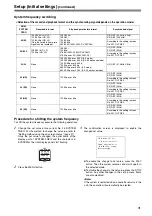
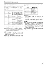
Procedure for shifting the system frequency

To shift the system frequency execute the following operations.

1

Change the set value of menu item No. 25 SYSTEM
FREQ. For the method to change the set value, refer to
"Setting method using the on-screen menus" (page 27) .
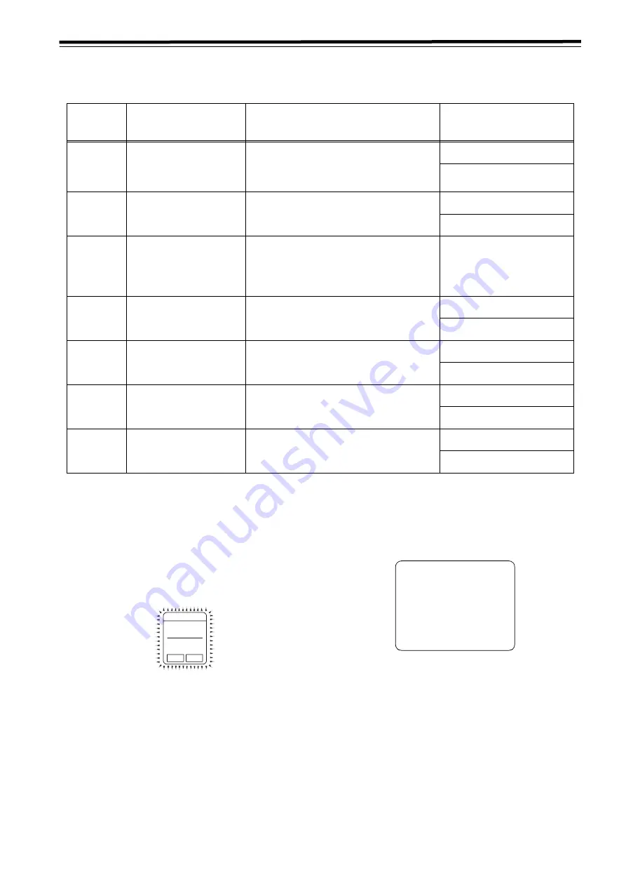
Once the set value is changed, the outer frame of the
display part of SYSTEM FREQ and the characters in
SYSTEM on the front display panel start flashing.

2

Press the MENU button.

3

The confirmation screen is displayed to enable the
changed set value.

z

To enable the change to set value, press the PLAY
button. Then the system resumes and starts again in
the selected mode.

z

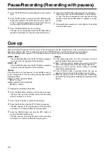
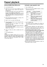
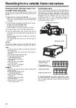
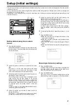
To disable the change to the set value, press the STOP
button. Any other changes in the set up menu items
are also disabled.

<Note>

If the system is restarted when a cassette remains in the
unit, the cassette will automatically be ejected.

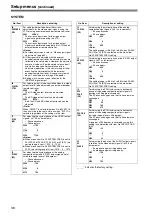
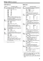
<Selection of the record and playback format and the synchronizing signal depends on the operation mode>

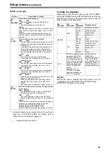
NO.25

SYSTEM 

FERQ

Recordable format

Playback permissible format

Synchronized signal

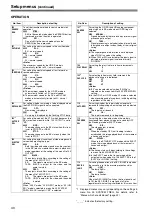
59/60

1080/59.94i (HD_LP)
720/59.94p (HD_LP)
720/60.00p (HD_LP)
(Only the variable frame rate 
signal can be recorded.)

1080/59.94i
1080/60i
720/59.94p
720/60.00p
480/59.94i (50M, 25M, DV, DVCAM)

HD_REF (59.94Hz, 60Hz)
SD_REF (59.94Hz)

According to the setting in menu 
No. 031 OUT REF.

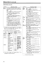
50i/25P

1080/50i (HD_LP)
720/50p (HD_LP)

1080/50i
720/50p
576/50i (50M, 25M, DV, DVCAM)
576/25p over 50i (50M, 25M, DV)

HD_REF (50Hz)
SD_REF (50Hz)

According to the setting in menu 
No. 031 OUT REF.

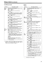
23/24

None

1080/23.98p over 59.94i [2:3 mode]
1080/23.98p over 59.94i [2:3:3:2 advance mode]
720/23.98p over 59.94p
720/24p over 60.00p
480/23.98p over 59.94i [2:3 mode]
480/23.98p over 59.94i [2:3:3:2 advance mode]

HD_REF (47.96Hz, 48Hz)

25 (HD)

None

720/25p over 60p

HD_REF (50Hz)
SD_REF (50Hz)

According to the setting in menu 
No. 031 OUT REF.

25 (SD)

None

720/25p over 60p

HD_REF (50Hz)
SD_REF (50Hz)

According to the setting in menu 
No. 031 OUT REF.

50 (HD)

None

720/50p over 60p

HD_REF (50Hz)
SD_REF (50Hz)

According to the setting in menu 
No. 031 OUT REF.

50 (SD)

None

720/50p over 60p

HD_REF (50Hz)
SD_REF (50Hz)

According to the setting in menu 
No. 031 OUT REF.

S

Y

S

TEM

59.94  60
50/25P

s

F

2

3

.9

8

25

24
50

HD

S

D

SETUP-MENU SET OK?

  YES<PLAY>/NO<STOP>

S

ystem


menu


item

 N

o.

25 

(SYSTEM FREQ) 

setting

has been changed.

Summary of Contents for AJ-HD1400E

Page 1: ...Printed in Japan VQT0X83 1 D Digital HD Video Cassette Recorder Operating Instructions Model No AJ E Before operating this product please read the instructions carefully and save this manual for future use P ENGLISH ...

Page 2: ...imply that it is grounded and the installation is not necessarily safe For your safety if in any doubt about the effective grounding of the equipment or power outlet please consult a qualified electrician CAUTIONS In order to maintain adequate ventilation do not install or place this unit in a bookcase built in cabinet or any other confined space To prevent risk of electric shock or fire hazard du...

Page 3: ...armful interference to radio communications Operation of this equipment in a residential area is likely to cause harmful interference in which case the user will be required to correct the interference at his own expense Warning To assure continued FCC emission limit compliance the user must use only shielded interface cables when connecting to external units Also any unauthorized changes or modif...

Page 4: ...his appliance is supplied with a moulded three pin mains plug for your safety and convenience A 13 amp fuse is fitted in this plug Should the fuse need to be replaced please ensure that the replacement fuse has a rating of 13 amps and that it is ap proved by ASTA or BSI to BS1362 Check for the ASTA mark or the BSI mark on the body of the fuse If the plug contains a removable fuse cover you must en...

Page 5: ...ing from a variable frame rate camera 26 Recording the HD SDI output signal from a variable frame rate camera 26 Field displacement 26 Setup initial settings 27 Setting method using the on screen menus 27 Returning to the factory settings 27 Setting the user defaults 28 User default loading method 29 Menu protection method 30 Menu protection release method 30 System frequency switching 31 Procedur...

Page 6: ...rding rate 100 Mbps which is four times as high as that for existing DVCPRO formats 1080i or 720p NTSC or PAL selectable By switching the settings provided for the video signal input 1080i 59 94 Hz or 720p 59 94 Hz on the setup menu the unit can record and playback each signal and also playback NTSC SD material The unit also supports the PAL mode Playback of 1080i 50 Hz record and playback of 720P...

Page 7: ...ernal device regeneration to an external time code is possible Since the backup function using a backup battery is incorporated in the TCG time code generator time codes during free run operations are retained even if the power of the unit is turned off Joystick and variable speed playback The unit is equipped with a joystick stick controller for use of the search function during variable speed pl...

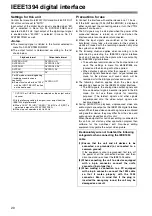
Page 8: ...unit s 9 pin remote control connector enables it to be operated with an external remote controller z IEEE1394 digital input output Set to this position when controlling this unit with the AV C command of the 9 pin REMOTE REMOTE of HD SDI IEEE1394 Note When any of the settings below is established no signals will be output from the IEEE1394 digital interface z When 60 24 is selected as the menu ite...

Page 9: ... level meter FULL mode The standard scale to 0 dB is selected FINE mode The scale in 0 5 dB increments is selected The position indicates the standard level of 20 dB For AJ HD1400P or 18 dB For AJ HD1400E See page 12 MONITOR SEL button This button is used to select the audio signals which are to be output to the AUDIO MON L and R connectors Each time the button is pressed the audio signals to be o...

Page 10: ...the TC or UB values MENU DIAG button When the connector that is selected in menu No 005 SUPER is used When this button is pressed the setup menus are displayed on the TV monitor and the setup menu numbers are displayed on the unit s display panel When it is pressed again the setup menu settings are exited and the original status is restored When the button is pressed while holding down the PF butt...

Page 11: ...d playback and menu setting operation become impossible SEARCH button When this button is pressed the search mode is established PLAY button When this button is pressed playback starts When this button and the REC button are pressed together recording starts REC button When this button is pressed together with the PLAY button recording starts When it is pressed during playback a search fast forwar...

Page 12: ... menu No 25 SYSTEM FREQ VFR Variable Frame Rate lamp This lamp lights when a tape 24 25 50PsF from a variable frame rate camera is played back after selecting the frame rate converter and when conversion is performed normally If the tape and selected frame rate conversion function for play back do not match the lamp flashes on and off Select the frame rate conversion function in menu No 25 SYSTEM ...

Page 13: ...menu item No 114 REC INH LAMP Channel condition lamps These lamps light to indicate the error rate status Green This lights when the error rates for the video and audio playback signals are both at acceptable levels White This lights when the error rate for the video or audio playback level has increased The playback picture and sound remain unaffected even while this lamp is lighted Red This ligh...

Page 14: ... the regular voltage and the unit is available An AC source cannot be connected to this terminal DC OUT socket This is the DC 12V output socket Power is supplied from here to the external remote controller AJ A95 optional accessory The DC power cable is packed together with the AJ A95 Fuse holder This holds the AC 250 V 2 5 A fuse time lag type Note Use the fuse specified by Panasonic ENCODER REMO...

Page 15: ... Lch Rch These are the output connectors for the analog audio signals It is possible to interlock Lch Rch to the volume control knob for headphones by adjusting menu No 712 MONI OUT appropriately AUDIO MONITOR connectors These are the audio monitor output connectors These connectors output the monitor selection channels It is possible to interlock these connectors to the volume control knob for he...

Page 16: ... from the HD SDI output and analog component output connectors z All the HD SDI output SD SDI output video output analog component output audio output and TC output signals are output in phase with the REF input In the 59 94 Hz 60 Hz or 50 Hz mode Input signals Menu item No 031 REF_IN INPUT AUTO HD_REF SD_REF INPUT 1 HD_REF_IN Input HD_REF_IN HD_REF_IN Internal SD INPUT Not input HD_REF_IN HD_REF_...

Page 17: ...IN frequency Complies with HD REF IN frequency 59 94Hz Complies with menu item No 030 frequency SD_REF_IN Input 59 94Hz Complies with menu item No 030 frequency 59 94Hz Complies with INPUT frequency Not input 59 94Hz Complies with menu item No 030 frequency 59 94Hz Complies with menu item No 030 frequency None Input Complies with INPUT frequency Complies with menu item No 030 frequency 59 94Hz Com...

Page 18: ...consumer use DV and DVCAM cassette tapes minimize the number of times the tapes are cued up at the same locations as much as possible z When consumer use DV and DVCAM cassette tapes are used the maximum time for STILL TIMER is set to 10 seconds It is recommended that tapes bearing the Panasonic brand be used as the consumer use DV tapes M cassettes Tapes capable of up to 33 minutes of recording or...

Page 19: ...osite signals Audio monitor signals Reference signal Reference signal To REMOTE CONTROL connector Audio output signals Video output signals Audio output signals Video output signals Video input signals Audio input signals Video monitor signals Audio monitor signals Notes z When disconnecting the remote signals 9P from one component and re connecting them to another component check the settings etc...

Page 20: ...analog video output signals and time code output signals become irregular in the EE mode Do not use these signals for recording purposes The teletext signals and other signals superimposed onto the video output signals also become irregular z During SLOW STILL playback unprocessed video and audio signals are output as the IEEE1394 digital interface output When these video and audio signals are mon...

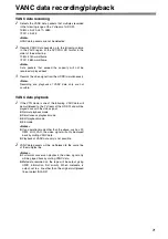
Page 21: ... possible VANC data playback 1 If the VTR mode is one of the following VANC data will be multiplexed to the Y stream of the HD SDI and will be played back with the video signal z Normal playback mode z Simultaneous playback mode z Edit playback mode z EE mode Notes z If an operation mode other than the above such as FF REW JOG VAR the video signal will only be played back by muting VANC data z Pla...

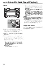
Page 22: ...upward the tape travels in 1 frame increments in the forward direction when it is inclined downward it travels in 1 frame increments in the reverse direction Slow playback is performed if the stick is held at the top or bottom position z If the SEARCH button is pressed while the joystick is pressed to one side the current speed is maintained even if the joystick is released Pressing the STOP PLAY ...

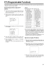
Page 23: ... The settings for the PF buttons are retained but will be updated once save operations are executed again Operation using the PF buttons 1 When the PF button is pressed the registered items are displayed on the monitor screen which is output from the VIDEO MON connector 2 Press the PF1 PF2 or PF3 button that corresponds to the item whose setting is to be changed Each time the button is pressed the...

Page 24: ...ss the REW button while the STOP button is pressed to cue up to the starting point of the recording Note If the time code is not successive it is impossible to cue up to the starting point of the recording properly Execute the following settings z Menu item No 154 AUTO BACK REC P or ALL z Menu item No 503 TCG MODE REGEN or AUTO 1 Execute the recording with pauses 2 Press the REW button while the S...

Page 25: ...u item No 160 MEMORY MODE and select the repeat playback mode 3 Press the MENU button A confirmation screen now appears The settings are stored in the memory if the PLAY button is now pressed Notes z The picture quality deteriorates when repeat playback is initiated for the same tape over and over again As a general rule of thumb replace the tape with a new one after playing back the tape for abou...

Page 26: ...he following settings are then invalid z TCG switch on the front panel REGEN PRESET EXT z Menu No 503 TCG_MODE SW AUTO z Menu No 505 TCG_REGEN TC UB TC UB z Menu No 507 TC_SOURCE EXT_L SLTC SVITC NORMAL Time code and user bits are recorded according to the following settings z TCG switch on the front panel REGEN PRESET EXT z Menu No 503 TCG_MODE SW AUTO z Menu No 505 TCG_REGEN TC UB TC UB z Menu N...

Page 27: ...the left 4 Incline the joystick up and down to select the item to change the setting The cursor on the select screen moves up and down and the item number flashes on the counter display 5 Incline the joystick right and left while pressing the SEARCH button at the changing position The set value on the settings screen and the set value in the counter display flash the value changes each time the jo...

Page 28: ... displayed on the video monitor and the names are displayed in the counter display 2 Follow the procedure described in Setting method using the on screen menus page 27 2 6 and adjust the desired settings 3 Press the RESET button The mode for this unit will change to the default setting mode and the default setting screen will be displayed on the video monitor 4 Incline the joystick up and down to ...

Page 29: ...ystick The mode for this unit changes to the LOAD mode the LOAD screen is displayed on the video monitor and the item name is displayed in the counter display 4 Incline the joystick up and down to adjust the cursor on the LOAD screen to the USER ALL each value from 1 to 3 position and press the joystick z When loading a set value other than SYSTEM menu in memory move the cursor to USER NOT SYSTEM ...

Page 30: ...switch to the menu protect mode z If the MENU button is pressed while the menu protect mode is set the message MENU PROTECT is displayed on the video monitor and the menu is displayed Note To enable ordinary menu operation while the menu protection mode is set press the MENU button when pressing the COUNTER button on the front panel Menu protection release method 1 Press the MENU button when press...

Page 31: ...t Playback permissible format Synchronized signal 59 60 1080 59 94i HD_LP 720 59 94p HD_LP 720 60 00p HD_LP Only the variable frame rate signal can be recorded 1080 59 94i 1080 60i 720 59 94p 720 60 00p 480 59 94i 50M 25M DV DVCAM HD_REF 59 94Hz 60Hz SD_REF 59 94Hz According to the setting in menu No 031 OUT REF 50i 25P 1080 50i HD_LP 720 50p HD_LP 1080 50i 720 50p 576 50i 50M 25M DV DVCAM 576 25p...

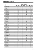
Page 32: ...S 009 CHARA TYPE 020 SYS FORMAT No No No No No 022 PB FORMAT 023 FORMAT SEL 030 HD FREQUENCY No No No No No 031 OUT REF No 032 REC REF No No No No No No 100 SEARCH ENA 101 SHTL MAX 102 FF REW MAX 104 REF ALARM 105 AUTO EE SEL No No No No No 106 EJECT EE SEL 107 EE MODE SEL No No No No No 108 PLAY DELAY 109 CAP LOCK No No No No No 110 AUTO REW 112 FRZ MODE SEL 114 REC INH LAMP 115 EJECT SW INH No N...

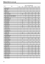
Page 33: ...No 504 RUN MODE No No No No No 505 TCG REGEN No No No No No 506 REGEN MODE No No No No No 507 EXT TC SEL No No No No No 508 BINARY GP No No No No No 509 PHASE CORR 510 TCG CF FLAG No No No No No 511 DF MODE No No No No No No 512 TC OUT REF No No No No No 513 VITC OUT 514 HD EMBD VITC No No 515 HD EMBD LTC No No 601 VIDEO INT SG No No No No No 602 SDI IN MODE No No No No No 603 V MUTE SEL 604 FREEZ...

Page 34: ...1 CH1 IN LV No No No No No 702 CH2 IN LV No No No No No 706 CH1 OUT LV 707 CH2 OUT LV 710 MONIL OUT LV 711 MONIR OUT LV 712 MONI OUT 724 REC CH3 4 No No No No No 730 REC CUE No No No No No 731 PB FADE 732 EMBEDDED AUD 746 MONI CH SEL 750 ANA CH1 2 SEL 759 DV PB ATT No No No No No 760 REC PT MUTE No No No No No 762 AUD RATE CON 765 CUE OUT SEL 781 IN IMP SEL No No No No No 782 EMB CH SEL 783 AUDIO ...

Page 35: ...ustments can be performed from both the external encoder remote controller and setup menus Notes z Use the MT 200 2000 manufactured by Musashi and recommended by Panasonic as the external encoder remote controller However its VIDEO PHASE SYNC PHASE and SC PHASE controls will not work During menu operations and operations using the PF function operations from the external encoder remote controller ...

Page 36: ...ments Phase advances Phase delays 0000 1100 1100 0 2200 1100 Notes z When menu item No 25 SYSTEM FREQ is set to 50i 25P 25 HD 25 SD 50 HD or 50 SD the setting range is from 1320 0 1320 z When menu item No 25 SYSTEM FREQ is set to 23 24 the setting range is from 1375 0 1375 14 SYS SC SD For adjusting the system phase of the analog composite output and SD SDI output signals total variable range of o...

Page 37: ...tting 001 LOCAL ENA For setting the operable buttons on the front panel when the REMOTE LOCAL switch is set to REMOTE 0000 DIS None of the buttons can be operated 0001 ST EJ Only the STOP and EJECT buttons can be operated 0002 ENA1 All of the buttons with the exception of COUNTER and RESET can be operated 0003 ENA2 All of the buttons can be operated 002 1 TAPE TIMER For setting how the time is to ...

Page 38: ...ed onto the display when a warning or error occurs z REC TIME and REC DATE are displayed only during DV or DVCAM playback The operation mode is displayed with the DVCPRO HD LP DVCPRO HD DVCPRO50 or DVCPRO format 007 CHARA H POS For setting the horizontal position at which the superimposed characters are to be displayed 0000 0 0006 6 0037 37 Note Press the joystick and tilt up down and right left t...

Page 39: ... reference is used 0002 HD REF The HD REF input signal serves as the reference If this signal is not available the unit s internal reference is used 0003 SD REF The SD REF input signal serves as the reference If this signal is not available the unit s internal reference is used 0004 E AUTO When the editing mode is selected the state is the same as when set to INPUT When any mode other than the edi...

Page 40: ... GRAY is output for the video and the audio is muted Note When 23 24 mode 25 HD SD mode or 50 HD SD mode is selected in menu No 25 SYSTEM FREQ BLACK is output if EE is selected No Item Description of setting 107 1 EE MODE SEL For setting the HD SDI and HD analog component output signals in EE mode when HD SDI input is selected 0000 NORMAL Signals delayed by the time taken by internal signal proces...

Page 41: ... for condensation is not activated even if ON is selected 140 1 OUTPUT For selecting the output signals 0000 EE In the STOP mode The input signals selected by the setting of the INPUT SELECT button are output During recording or editing The input signals selected by the setting of the INPUT SELECT button are output 0001 TAPE In the STOP mode The signals played back from the tape are output During ...

Page 42: ... 2 1080 50i 2 1080 25p over 50i 2 720 50p TYPE1 720 25p over 50p TYPE1 No Item Description of setting 160 MEMORY MODE For setting the repeat playback mode 0000 OFF No repeat playback normal operation 0001 M STOP The tape stops near the BEGIN point when it is fast forwarded or rewound 0002 REPT1 When the tape reaches the END point it is rewound to the BEGIN point and stops 0003 CONT When the tape r...

Page 43: ...044 15 0 Note When this item has been set to a voltage level close to 15 0 V the counter display may flash even when an AC power source is being used 184 1 TYPE B END For setting in increments of 0 1 V the voltage level at which the TYPE B battery selected as the menu item No 180 BATTERY SEL item is to be automatically turned off 0000 10 6 0018 12 4 0034 14 0 190 2 V IN SEL INH For selection of th...

Page 44: ...001 CH1 The analog CH1 edit presets are followed 0002 CH2 The analog CH2 edit presets are followed 0003 CH1 2 The analog CH1 or CH2 edit presets are followed 321 1 EDIT RPLCE2 As with menu item No 320 the VTR s CH2 edit presets are set to ON or OFF following the analog audio signals specified by the controller 0000 N DEF Not set 0001 CH1 The analog CH1 edit presets are followed 0002 CH2 The analog...

Page 45: ...nute for DV or DVCAM tape No Item Description of setting 500 1 VITC BLANK For setting whether to output the VITC signal at the position which is set using menu items No 501 VITC POS 1 and No 502 VITC POS 2 0000 BLANK The VITC signal is not output 0001 THRU The VITC signal is output Note This setting takes effect only with the SD output analog composite output and SD SDI output 501 1 2 VITC POS 1 F...

Page 46: ...osed onto the HD serial output signals 508 1 BINARY GP For setting the usage status for the user bits of the time code generated by the TCG 0000 000 No character set specified 0001 001 8 bit character set complying with the ISO646 and ISO2022 standards 0002 010 Undefined 0003 011 Undefined 0004 100 Undefined 0005 101 Page line 0006 110 Undefined 0007 111 Undefined 509 PHASE CORR For setting whethe...

Page 47: ...r of the analog HD component signals are muted 619 1 V_FILTER This is used to select the method to process the images using the vertical filter during down conversion 0000 FIELD The images are processed by field basis 0001 FRAME The images are processed by frame basis Note When FRAME has been selected the resolution is improved but the images may flicker 620 1 DOWNCON MODE For setting the image pr...

Page 48: ...ffect when CMPNT has been selected as the menu item No 650 setting 659 Pb LVL SD DW For adjusting the PB level of the SD SDI output and analog composite output to 0 dB to 3 dB 0000 0 0 1000 100 0 1413 141 3 Note This setting takes effect when CMPNT has been selected as the menu item No 650 setting No Item Description of setting 660 Pr LVL SD DW For adjusting the PR level of the SD SDI output and a...

Page 49: ...EDH SD DW For setting whether to superimpose EDH onto the SD SDI output 0000 OFF EDH is not superimposed 0001 ON EDH is superimposed 685 1 ESR MODE SD DW For selecting the mode of the edge subcarrier reduction ESR operation in the playback circuit 0000 OFF ESR is forcibly turned off 0001 AUTO ESR is automatically set to ON or OFF depending on the unitÅfs operation No Item Description of setting 68...

Page 50: ...This converts video images shot with the cine gamma FilmREC mode of the Varicam into the Cineon curve appropriate for film recording Notes z Gamma correction is effective in the following conditions When the VTR operation mode is VV TAPE and 720p is displayed in the system format However during cross convert from 720p 1080i gamma correction is not effective for SD output z When ON is selected the ...

Page 51: ...ck 0001 CH1 Audio input CH1 signal 0002 CH2 Audio input CH2 signal 0003 CH3 Audio input CH3 signal 0004 CH4 Audio input CH4 signal 0005 CH5 Audio input CH5 signal 0006 CH6 Audio input CH6 signal 0007 CH7 Audio input CH7 signal 0008 CH8 Audio input CH8signal 0009 CH1 2 Audio input CH1 CH2 mixed signal 0010 CH3 4 Audio input CH3 CH4 mixed signal 0011 CH5 6 Audio input CH5 CH6 mixed signal 0012 CH7 8...

Page 52: ...ttings cannot be performed on a channel by channel basis 765 CUE OUT SEL For setting whether to output the analog CUE signal to CH1 2 for the analog audio output 0000 OFF The analog CUE signal is not output The PCM audio signal is output when the speed range is less than j1 0k to 1 0k while the no audio signal is output at any other speed 0001 ON The analog CUE signal is output The PCM audio signa...

Page 53: ... signals simply pass through 0001 LOCK Forcible conversion to the LOCK mode no frequency conversion 0002 LOCK48 Forcible conversion to 48kHz 2CH LOCK No Item Description of setting 892 1 DIF SIG CMD For setting how to reply when signals requesting a confirmation of the format is sent from an external device connected by the IEEE1394 digital interface 0000 50M DVDPRO50 is forcibly returned 0001 25M...

Page 54: ... the selected user 3 loaded Note Set value for SYSTEM menu is not loaded A04 PF1 ASSIGN The setup menu item is stored to the PF1 button Note Part of the items listed on the menu cannot be saved For details refer to PF Programmable Function page 23 A05 PF2 ASSIGN The setup menu item is stored to the PF2 button Note Part of the items listed on the menu cannot be saved For details refer to PF Program...

Page 55: ...by the TC PRESET button 5 To preset the time code or user bit take the following steps 1 Set the TCG switch to PRESET 2 Select TC or UB using the COUNTER button 3 When the TC PRESET button is pressed operation is transferred to the setting mode and the setting digits start flashing on the counter display 4 Operate the joystick and set the preset value Left right for moving between digits Up down f...

Page 56: ...UTO BACK is set to OFF scene to scene continuity will be a normal recording TCG switch Menu No 507 EXT TC SEL Selected video input signal Recorded timecode SBC area VAUX area INT REGEN PRESET 1394 Internal TCG value Refer to the following table Timecode on IEEE1394 digital input VAUX area HD SDI SVITC on input video signal 3 EXT EXT_L 1394 Timecode on IEEE1394 digital input SBC area Timecode on IE...

Page 57: ...been read correctly from the tape z When the 23 98 24 Hz 25 Hz HD SD or 50Hz HD SD mode is selected in menu No 25 SYSTEM FREQ indications on the CTL and TCR will be Characters displayed The background of characters superimposed on the display can be changed using menu No 009 CHARA TYPE Display position The position of the characters superimposed on the display can be changed using menus No 007 CHA...

Page 58: ...nly moved from a cold location to a hot or humid location When moving the unit to locations such as these leave it standing for about 10 minutes rather than switching on the power immediately If condensation occurs in the unit E 20 will flash on the counter display and the cassette will be automatically ejected Leave the unit with the power on until E 20 is cleared from the display Maintenance Bef...

Page 59: ... by the dealer when maintenance work is performed z No operations can be performed using the SEARCH button or the joystick while the DIAG menu is displayed 1 2 3 CH1 5 CH2 6 CH3 7 CH4 8 REC PB CH1 CH2 CH1 CH2 PB NO Item Description Ser Displays the unit s serial No H00 OPERATION Displays the time that the power has been supplied in one hour units H01 DRUM RUN Displays the time that the drum has be...

Page 60: ... at the start of operation EE mode when the REC button is pressed NO INPUT If there are no input signals with the exception of the analog audio signals supplied to the connectors selected by the INPUT SELECT button the NO INPUT display will appear for the first two seconds at the start of operation EE mode when the REC button is pressed Warning messages See error message table When a warning occur...

Page 61: ...e not DVCPRO DV format signals Check that the 1394 input has been connected properly No recording o perations are possible E 90 NOT 1X 100M SIG This appears when the initialization process fails during communication via the IEEE1394 digital interface Check the input signal Operation continues 1 E 16 INVALID VIDEO SIG This appears when the compressed video signals supplied from the IEEE1394 digital...

Page 62: ...lay Note If the cassette does not move down inside the machine even when 6 seconds have elapsed since the cassette was inserted the VTR is transferred to the eject mode Set the POWER switch to OFF and then to ON again STOP E 31 LOADING MOTOR If the unloading operation is not completed within 6 seconds this error number flashes on the display Note When the loading operation is not completed within ...

Page 63: ... again STOP E 69 T REEL TORQUE ERR If excess torque being applied to the take up reel motor is detected the error number flashes on the display Set the POWER switch to OFF and then to ON again STOP E 70 S REEL TORQUE ERR If excess torque being applied to the supply reel motor is detected or an abnormal current flowing to the current detection resistor is detected this error number flashes on the d...

Page 64: ...ivated by this and it makes a latching sound Ignore the sound and turn the gear through about 10 revolutions Note Turning the gear more than necessary will strain the cassette possibly resulting in tape damage 3 Check that the posts have unloaded the tape and that the tape is completely housed inside the cassette 4 Once the tape has been completely returned inside the cassette case use the Phillip...

Page 65: ... mode Tape timer accuracy 2 frames when continuous CTL signal is used For slow replay at half speed or less errors may occur in the CTL count VIDEO _Digital video Sampling frequency Y 74 25 MHz PB PR 37 125 MHz Quantizing 8 bits Video compression system DCT variable length code Video compression ratio 1 6 7 Error correction Reed Solomon product code Video recording bit rate 100 Mbps _Video input c...

Page 66: ... ns increments 59 94 Hz 858 samples 50 Hz 864 samples Composite video output SC phase 180 or more AUDIO _Digital audio Sampling frequency 48 kHz synchronized with video Quantizing 16 bits Frequency response 20 Hz to 20 kHz 1 dB at reference level Dynamic range More than 85 dB 1 kHz emphasis OFF Distortion Less than 0 1 1 kHz emphasis OFF reference level Crosstalk Less than 80 dB 1 kHz between 2 ch...

Page 67: ... pins k1 DC 12 V 250 mA for AJ A95 1394 input output connector Connector 6 pin type Transmission rate 400 Mbps 200 Mbps 100 Mbps selectable Transmission data Compliant with IEEE1394 1995 Compliant with IEC 61883 Part1 Part2 Control command Compliant with AV C command set Accessories Power supply cord k 1 AJ HD1400P Power supply cord k 2 AJ HD1400E Weight and dimensions shown are approximate Specif...

Page 68: ...n Disposal for Users of Waste Electrical Electronic Equipment private households This symbol on the products and or accompanying documents means that used electrical and electronic products should not be mixed with general household waste For proper treatment recovery and recycling please take these products to designated collection points where they will be accepted on a free of charge basis Alte...

Reviews: