background image

- 169 -

Advanced network setting tab [Advanced]

Click the [Advanced] tab in the network setup screen [Network].
Settings relating to the FTP, NTP, UPnP, and HTTPS functions are performed here.
Click the links to each item to move to the respective setting page.

¥

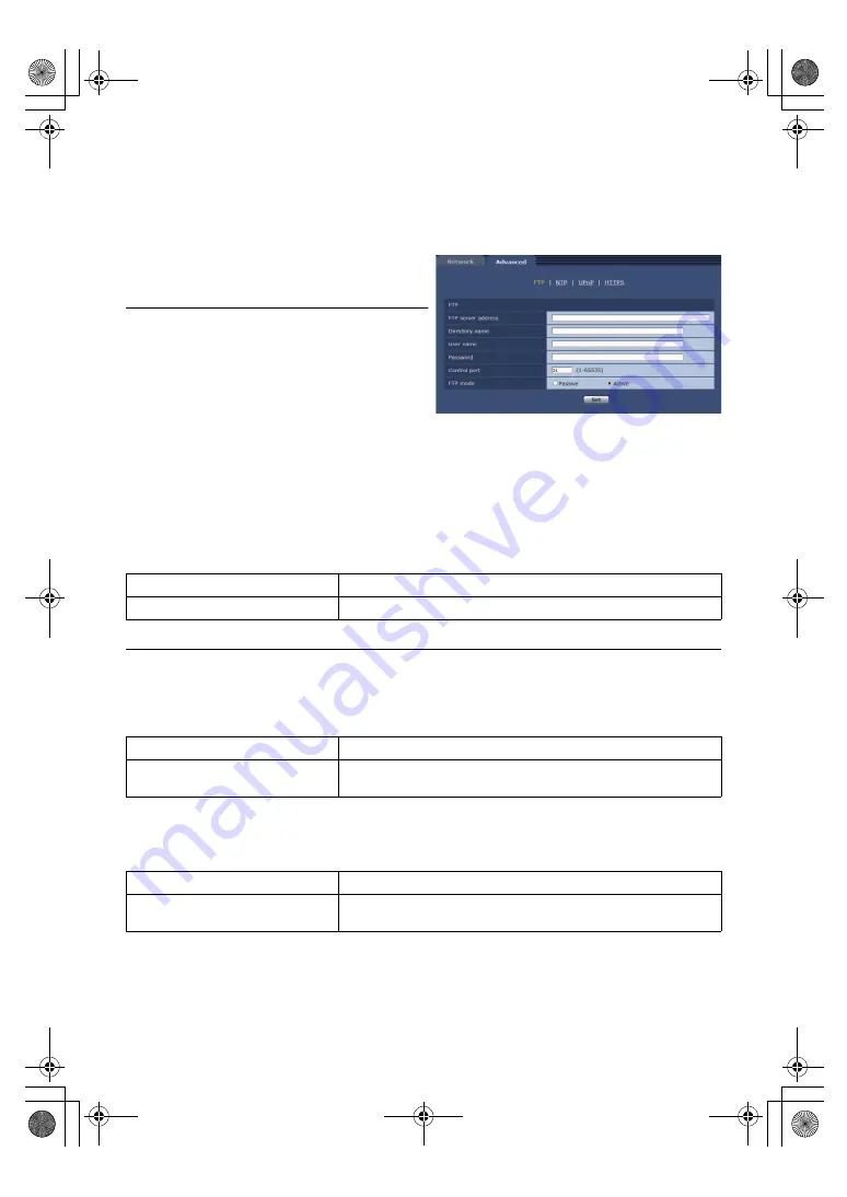
FTP

Configure settings related to the FTP server.
This item’s setting is reflected when the [Set] button is 
pressed.

CGI control from an external device is required to use 
the FTP function.

The FTP function is not available in the following cases.

j

During PRE-REC or recording

j

While the unit is in Playback Mode or standby mode

j

While a clip is being downloaded from the SD card to 
the PC (

l

188

)

To use the FTP function, set the priority mode to “REC/
PB” or “REC/PB(4K)”. For details, refer to “Priority 
mode tab [Priority Mode]” (

l

144

).

The following operations cannot be performed while data is being transferred to an FTP server.

j

Recording to the SD card

j

Displaying the List screen

j

Switching to Playback Mode or standby mode

FTP server address

Enter the IP address or host name of the FTP server to which image data is to be sent.

Factory settings: 

blank

To enter the host name of [FTP server address], you need to configure the [DNS] settings on the [Network] tab of the 
network setup screen [Network]. (

l

167

)

Directory name

Enter the name of the directory to save the video data to be sent.

Factory settings: 

blank

User name

Enter the user name (login name) for accessing the FTP server.

Factory settings: 

blank

Maximum number of characters

0 to 128 half-size characters

Characters that can be entered

Half-size alphanumeric characters, half-size symbols 

: . _ -

Maximum number of characters

0 to 256 half-size characters

Characters that can be entered

Half-size alphanumeric characters, half-size symbols
However, the following characters cannot be entered. " & :

Maximum number of characters

0 to 32 half-size characters

Characters that can be entered

Half-size alphanumeric characters, half-size symbols
! # $ % 

´

 ( ) * + , - . / = ? @ [ ] ^ _ ` { | } ˜

AG-UMR20PJ.EJ(DVQP1321ZA)_E.book  169 ページ  2017年5月22日 月曜日 午後2時11分

Summary of Contents for AG-UMR20P

Page 1: ...Portable Recorder Model No AG UMR20P AG UMR20E Please read these instructions carefully before using this product and save this manual for future use DVQP1321ZA ENGLISH PJ EJ F0517SQ0 until 2017 05 31...

Page 2: ...VRQ HO D DOiEEL ZHEROGDOUD DWYLH X DL LHJ WX LQIRUP FLMX SDU GUR EX XQ VNDW WX VYDU JXV SD L RMXPXV SDU R SURGXNWX DSPHNO MLHW W O N QRU G WR W PHN D YLHWQL LHWXYL HL UHLNLD VDXJRV LQIRUPDFLMRV LU VYD...

Page 3: ...urtains and similar items Do not place sources of naked flames such as lighted candles on this unit CAUTION About using a headphone Excessive sound pressure from earphones and headphones can cause hea...

Page 4: ...ower plug can be unplugged from the socket outlet immediately The unit is in the standby condition when the AC adaptor is connected The primary circuit is always live as long as the AC adaptor is conn...

Page 5: ...re they exit from the apparatus 11 Only use attachments accessories specified by the manufacturer 12 Use only with the cart stand tripod bracket or table specified by the manufacturer or sold with the...

Page 6: ...e with the instructions may cause harmful interference to radio communications However there is no guarantee that interference will not occur in a particular installation If this equipment does cause...

Page 7: ...For USA only Disposal may be regulated in your community due to environmental considerations For disposal or recycling information please visit Panasonic website http www panasonic com environmental...

Page 8: ...he device to suddenly stop during recording or while On Air 2 If the device is a Studio Monitor A Power Management function may cause video for the confirmation of whether a signal is normal or whethe...

Page 9: ...ommend using a cable with a length of 3 m 9 84 feet or less Make sure to use the supplied cords If you use optional accessories use the cords and the cables supplied with them Do not extend the cords...

Page 10: ...tached with the terminal part in a deformed state this unit or battery charger may be damaged Do not throw old battery into fire Heating a battery or throwing it into a fire may result in an explosion...

Page 11: ...d area its LCD monitor will be slightly darker than usual immediately after the unit is turned on The normal brightness will be restored when the unit s internal temperature rises It is possible to di...

Page 12: ...NCE OF THE PRODUCT FOR THE CASES INCLUDING BUT NOT LIMITED TO BELOW 1 ANY DAMAGE AND LOSS INCLUDING WITHOUT LIMITATION DIRECT OR INDIRECT SPECIAL CONSEQUENTIAL OR EXEMPLARY ARISING OUT OF OR RELATING...

Page 13: ...rs for example to prevent setting information stored on the unit from leaking over the network Do not install the camera in locations where the camera or the cables can be destroyed or damaged by pers...

Page 14: ...instructions are designed for use with models AG UMR20P AG UMR20E The illustrations and screen examples used in this document are of the AG UMR20P About Condensation When the lens of the Camera Head o...

Page 15: ...Time Code 62 Setting the User Information 64 Setting the Recording Counter 64 Using the TC data of the SDI output device 65 USER button 65 Setting the USER button 65 Using the USER button 66 Function...

Page 16: ...P 221 OTHER FUNCTION 226 NETWORK SETUP 228 MAINTENANCE 229 PLAYBACK SETUP 229 OPERATION 230 Display Indications 231 Messages 233 Warning Indications 237 Event log 239 Others Troubleshooting 242 About...

Page 17: ...20E Caution for AC Mains Lead FOR YOUR SAFETY PLEASE READ THE FOLLOWING TEXT CAREFULLY This product is equipped with 3 types of AC mains cable Appropriate mains cable must be used in each local area s...

Page 18: ...ed with an HD SDI output terminal and record video signals audio signals time code SLTC etc on the SD card This is suitable for long term backup recording etc Recording start and stop operation of thi...

Page 19: ...equivalent to 5C FB commercially available When connecting in SDI Mode it is possible to change the output method to the external device by setting SDI MODE SEL The video signal of the SDI output may...

Page 20: ...automatically recognize straight cables and crossover cables connected to the LAN terminal Connection with remote camera controller LAN cable A Camera head option cable B HDMI cable BNC cable 1 AG UM...

Page 21: ...illustrations of the Camera Head and SDI output device are omitted This unit will automatically recognize straight cables and crossover cables connected to the LAN terminal Connection to PC mobile ter...

Page 22: ...1 q diameter type screw longer than 8 mm 0 3 q in length this unit may be damaged 25 Exhaust opening cooling fan l 39 26 Speaker 27 DC input terminal DC IN l 24 226 Connect the DC 12 V power source Wh...

Page 23: ...button PUSH l 25 32 Battery holder l 25 33 SD Card slot cover l 28 34 Access lamp card 1 l 28 35 Card slot 1 l 28 36 Card slot 2 l 28 37 Access lamp card 2 l 28 38 Setting legs 24 24 30 31 32 38 38 33...

Page 24: ...G VBR118 supports quick charging It is recommended to charge with the AG BRD50 battery charger that supports fast charging For information on how to charge the battery refer to the Operating Instructi...

Page 25: ...t the battery until it clicks and locks Removing the battery Turn off the unit by pressing and holding the power button until the status indicator is turned off and remove while holding with hand so i...

Page 26: ...nd recordable time vary depending on the usage conditions such as high low temperature The batteries heat up after use or charging This is not a malfunction Use of the optional battery charger AG B23...

Page 27: ...iting To check the class see the labelled side etc of the card Preparation Preparation of SD cards Card type Capacity SDHC Memory Card 4 GB to 32 GB SDXC Memory Card 48 GB to 128 GB We do not guarante...

Page 28: ...rd j Turn the unit off j Insert and remove the USB Cable j Expose the unit to vibrations or shock Performing the above while the lamp is on may result in damage to data SD card or this unit Do not exp...

Page 29: ...ckwise Fix firmly so that there is no looseness This unit will start up in the CAM Mode when it is turned on after connection The Camera Head is turned on and recording is possible Removing the Camera...

Page 30: ...ns that cannot be set in the SDI Mode The following functions cannot be set on this unit in the SDI Mode Set on the SDI output device side j Switching Recording Mode l 43 j Adjustment of picture quali...

Page 31: ...ECONOMY BATT or ECONOMY AC have worked press the power button for 2 seconds or longer to turn on the unit l 226 Connecting or removing the Camera Head with this unit turned on may cause this unit and...

Page 32: ...nu l 34 Recording is possible s Recording or distribution is not possible 1 Clips recorded on an SD card can be downloaded to a PC and transferred to an FTP server 2 On the Live screen of this unit 4K...

Page 33: ...Standby Mode When PRIORITY MODE is set to IP or IP 4K press the MODE button to switch between Recording Mode and Standby Mode In Standby Mode this unit appears as follows j The status indicator flash...

Page 34: ...on the bottom item press the button to switch the page To adjust the numerical value by button operation In the menu for setting the numerical value after selecting the numerical display part press th...

Page 35: ...ouch screen with your finger Touch Touch and release the touch screen to select icon or picture Touch the center of the icon Touching the touch screen will not operate while you are touching another p...

Page 36: ...value using The year can be set between 2000 and 2035 3 Touch ENTER to complete the setting Touch the MENU button to close the menu screen The date and time function is driven by a built in lithium ba...

Page 37: ...a s5 00 Toronto New York Miami Lima r6 30 Yangon s6 00 Chicago Houston Mexico City r7 00 Bangkok Jakarta s7 00 Denver Phoenix r8 00 Beijing Hong Kong Kuala Lumpur Singapore s8 00 Vancouver Seattle Los...

Page 38: ...sed display and normal display switches every time the button is pressed The reversed display also reverses the horizontal and vertical directions of the buttons except for the following functions j Z...

Page 39: ...may be damaged When fixing to something other than a tripod pay attention to the following points j Use the tripod mounting hole to fix securely j Do not block the Camera Head inlet exhaust opening or...

Page 40: ...lection Set the system frequency of this unit Select the menu In Recording Mode In Playback Mode After you have changed the system frequency this unit will be restarted automatically By default the sy...

Page 41: ...4 clips that were generated by automatic splitting are played back in succession the changeover between them may not be smooth Recording stops momentarily when the continuous recording time reaches ap...

Page 42: ...lay recording This is simple Relay Recording It is possible to continuously record on the SD card in the other card slot even when the available capacity of the SD card runs out during the recording E...

Page 43: ...E FILE SELECT SCENE About Auto Mode In Auto Mode the following menu items are set automatically Their settings cannot be changed Controls that are disabled in Auto Mode In Auto Mode the following oper...

Page 44: ...enu item WB R GAIN l 202 WB B GAIN l 202 When the Auto White Balance Auto Black Balance is performed the setup for WB R GAIN and WB B GAIN will be set to 0 l 53 This function sets color saturation and...

Page 45: ...the noise reduction effect and the afterimage level Menu item NR CONTROL l 206 Color matrix setup function MATRIX Loads the preset color matrix data and compensates the saturation and phase accordingl...

Page 46: ...ris gain value and shutter speed at that point in time When the zoom magnification is at the maximum magnification the minimum focusing distance is approximately 1 5 m 4 9 feet When the zoom magnifica...

Page 47: ...en using a tripod we recommend that you set the Image Stabilizer to setting canceled Compared to O I S Hybrid O I S can produce stronger compensation Hybrid O I S performs compensation electronic on m...

Page 48: ...range and or The unit may switch to the macro range even when the distance to the subject is 1 5 m 4 9 feet or more depending on the subject Depending on the zoom magnification this unit may fail to...

Page 49: ...the setting Setting the peaking frequency of LCD DETAIL Select the menu In the following cases LCD DETAIL will be set to OFF and the setup cannot be changed j During Focus Assist l 51 CUSTOM AF STABI...

Page 50: ...n while pressing and holding the SHIFT button After Auto Focus is activated and Auto High Speed Focus is performed the focus point automatically tracks the focused subject at the center of the screen...

Page 51: ...Assist can also be used by pressing the USER button assigned as FA l 65 Focus Assist is not possible in following cases j During Recording Check l 71 j During Freeze Frame l 69 j When color bars are d...

Page 52: ...uttons to switch the White Balance mode Press the SET button after the adjustment is completed The multi manual icon will change to yellow By changing the WB R GAIN and WB B GAIN setup the hue for AWB...

Page 53: ...ite piece of paper in front of the lens 2 Set the White Balance mode to AWB A Ach or AWB B Bch 3 Perform the Auto White Balance by pressing or pressing and holding the button while pressing and holdin...

Page 54: ...ther switch to Auto Mode l 43 or set IRIS MODE to AUTO This cannot be set for the following cases j During Freeze Frame l 69 j During Infrared Recording Mode l 69 Depending on the zoom magnification t...

Page 55: ...CKLIGHT or touch the USER button icon To cancel press the USER button again or touch the USER button icon again appears when it is set It is also possible to set this item by following the menu path S...

Page 56: ...lowing operations is performed j Switching to Auto Gain Mode The gain value cannot be adjusted for the following cases j During Freeze Frame l 69 If the gain value is increased the noise on the screen...

Page 57: ...button icon To cancel Super gain press the USER button or touch the USER button icon again It is also possible to access this function by following the menu path SW SETUP SUPER GAIN ON OFF To change t...

Page 58: ...ding on the frame rate in REC FORMAT l 212 Synchro Scan values l 59 The shutter speed closer to 1 8000 is faster Shutter speed guide for fast moving subjects Refer to the table below to reduce afterim...

Page 59: ...nd shutter speed If you turn off the unit without pressing the power button by for example disconnecting the AC adaptor from the AC outlet the unit will not memorize the current zoom and focus positio...

Page 60: ...THROUGH during SDI Mode AUDIO SELECT cannot be set to LINE MIC or Plug in Power Mic Using an external microphone or audio equipment Connect an external microphone or audio equipment to MIC LINE IN ter...

Page 61: ...ADV j button or the AUDIO MON ADV i button while pressing and holding the SHIFT button l 76 AUDIO LEVEL setup cannot be changed when AUDIO SELECT is set to OFF or SDI Distortion of sound can be decre...

Page 62: ...es seconds and frames TC 00 00 00 00 hour minute second frame NDF TC 00 00 00 00 hour minute second frame DF The number of frames frame count per second varies depending on the frame rate in REC FORMA...

Page 63: ...uch Reset h is an abbreviation for hour m for minute s for second and f for frame 3 Touch EXIT to complete the setting This unit will adjust the time code in accordance with the frame rate of the REC...

Page 64: ...annot be used Setting the Recording Counter Recording Counter will display the recording time in seconds 0 00 00 hour minute second When REC COUNTER is set to TOTAL CLP 0 00 00 hour minute second When...

Page 65: ...possible to register functions to USER2 to USER13 in Playback Mode 2 Touch the item to register For the functions of the USER button that can be registered refer to page 67 Touch INHIBIT if not regist...

Page 66: ...there is no touch operation for a period of time the operation icons will disappear To display again touch the screen The display duration of operation icons can be changed in OPERATION ICONS DISPLAY...

Page 67: ...K ATW L ATW Lock s BACKLIGHT B Light Backlight Compensation s SPOTLIGHT S Light Spotlight Compensation s D ZOOM D ZM Digital Zoom s DRS DRS DRS s SUPER GAIN S Gain Super Gain s FRZ FRAME FRZ Freeze Fr...

Page 68: ...ries depending on the D ZOOM RATIO setting When using Digital Zoom the larger you set the zoom magnification the lower the picture quality becomes Digital Zoom is not possible in following cases j Dur...

Page 69: ...a clear image by positioning the center area of the screen over the subject Focus values may not be displayed correctly in Infrared Recording Mode l 48 The following menu items are not available in In...

Page 70: ...lows the recording of an image and audio to start before you press the recording REC PAUSE button AVCHD clips will record from approximately 3 seconds before and MP4 clips will record from approximate...

Page 71: ...n the MODE button is pressed j When the SD card is inserted removed j When the setting of REC FORMAT is changed l 212 Register REMOTE REC to a USER button l 65 This controls recording performed with a...

Page 72: ...It is not displayed when the ZEBRA DETECT 2 is set to OFF l 223 This function is not available in the following cases j When WFM is set to ON l 77 222 j During Freeze Frame l 69 You can record an ima...

Page 73: ...s no SDI input If you display color bars while an error message about SDI input is displayed on the unit s screen built in color bars will appear l 95 While built in color bars are displayed input inf...

Page 74: ...display3 Mode information display4 Normal display Regardless of the OPERATION ICONS DISPLAY setting l 225 the USER button icons are displayed for about 5 seconds while the Mode information display is...

Page 75: ...g is paused in Recording Mode j While a thumbnail screen is displayed in Playback Mode l 83 j While the list by date is selected l 88 Register FA to a USER button l 65 Sets the Focus Assist function l...

Page 76: ...The following operations are enabled even while the operations are locked j Recording and zoom operation with the wired remote control optional connected to the CAM REMOTE terminal j Operation from t...

Page 77: ...ed as WFM This function is not available in the following cases j When using Focus Assist l 51 j During Freeze Frame l 69 j When color bars are displayed l 73 WFM will be canceled in the following cas...

Page 78: ...tions and adjust their settings When the recording screen is displayed Switching on off of the LCD monitor FOCUS A Multi manual icon FOCUS Multi manual icon Function Usable modes CAM Mode SDI Mode ICO...

Page 79: ...n ICONS is selected l 43 Adjustment of the selected function is possible by pressing the buttons Functions Settings FOCUS s AE LEVEL Set SELECT SCENE to AUTO or set IRIS MODE GAIN MODE or SHUTTER MODE...

Page 80: ...e setup If the selected setting ND1 64 ND1 16 or ND1 4 does not match an ND filter setting recommended by this unit the recommended setting will be displayed on the screen blink for approximately 5 se...

Page 81: ...when the input signal is disrupted To set to anything other than OFF always turn on this unit and connect to a camera recorder in the recording pause status Recording control of the external device s...

Page 82: ...SEL is set to THROUGH during the SDI Mode If TCG is set to REC RUN the time code value may stay the same for a while at the beginning of a clip being recorded with an external device OUTPUT SETUP SDI...

Page 83: ...ystem frequencies is displayed in the thumbnail You can play them back by changing the SYSTEM FREQ setting If you have touched the recording mode option AVCHD After you have touched a recording format...

Page 84: ...TC j START UB j DATE j TIME ZONE j DURATION j REC MODE j FORMAT If you press the MODE button to switch between Recording Mode and Playback Mode the thumbnails of 9 clips will be displayed By displayin...

Page 85: ...L Motion picture compatibility This unit is based on AVCHD Progressive AVCHD Even if the devices used have compatible standards when playback of video recorded using another device is performed using...

Page 86: ...urn to normal playback when the button is pressed Slow motion Playback is performed continuously while the display is touched and held Normal playback is restored when you touch For slow rewind playba...

Page 87: ...k before printing in the store or on your printer Please refer to page 255 about approximate number of recordable pictures Repeat Playback Playback of the first clip starts after playback of the last...

Page 88: ...n cases such as those described below clips and still pictures are grouped separately on the date list and 1 2 may be added after the date j When the number of clips exceeds 99 j When the number of st...

Page 89: ...99 clips can be selected to be deleted When SINGLE is selected in Step 1 Touch the clip still picture to be deleted 3 When MULTI is selected in Step 1 Touch Delete To continuously delete other clips...

Page 90: ...a related to the clips still pictures may be deleted When still pictures recorded on an SD card by other products are deleted a still picture other than JPEG that cannot be played back on this unit ma...

Page 91: ...TE is selected When touched the date is selected and surrounded by red Touch the date again to cancel the operation Up to 99 clips or 99 dates can be set in succession 4 Touch EXIT when the copy compl...

Page 92: ...cting a wired remote control to the ZOOM S S terminal 2 5 mm 0 1 q diameter super mini jack allows you to remotely control the zoom and start stop recording Do not connect any device other than a wire...

Page 93: ...To watch images on an external monitor 4 3 or when both sides of the images do not appear on the screen Change the menu setting to display the images correctly Check the external monitor setting 1 Set...

Page 94: ...not be output to the SDI OUT terminal DOWN CONV setting LETTERBOX SQUEEZE OUTPUT SETUP CHAR OUTPUT ON or OFF OUTPUT SETUP SDI MODE SEL desired setting During CAM Mode THROUGH The Camera Head image ca...

Page 95: ...age signal is input Recording cannot be started if there is no image signal Do not stop the signal being output to the external device or disconnect the cable during recording This may cause the clip...

Page 96: ...changing between clips It may not be possible to change the setup of RESOLUTION depending on the combination of the recording format type and OUTPUT SEL If the setup value of RESOLUTION is an item th...

Page 97: ...erminal SDI OUT terminal HDMI OUT terminal 4K 2160 29 97p 1080p 1080 59 94i 1080 29 97p 1080 59 94i 1080 29 97p 1080i 1080 59 94i 1080 59 94i 720p DOWN CONV 480 59 94p 480 59 94p 4K 2160 23 98p 1080p...

Page 98: ...80 25 00p 1080 50 00i 1080 25 00p 1080i 1080 50 00i 1080 50 00i 720p DOWN CONV 576 50 00p 576 50 00p PS 1080 50 00p 1080p 1080 50 00i 1080 50 00i 1080i 1080 50 00i 1080 50 00i 720p DOWN CONV 576 50 00...

Page 99: ...4i 1080 29 97PsF 1080 59 94i 1 1080 59 94i 720p DOWN CONV 480 59 94p 4K 2160 23 98p 1080p 1080 23 98p 1080i 1080 59 94i 1080 23 98PsF 1080 59 94i 1 1080 59 94i 720p DOWN CONV 480 59 94p PS 1080 59 94p...

Page 100: ...OUT terminal HDMI OUT terminal SDI OUT terminal HDMI OUT terminal 4K 2160 25 00p 1080p 1080 25 00p 1080i 1080 50 00i 1080 25 00PsF 1080 50 00i 2 1080 50 00i 720p DOWN CONV 576 50 00p PS 1080 50 00p 10...

Page 101: ...0 23 98p 1080p Input signal without modification 1080 23 98p Input signal without modification 1080 23 98p 1080i 1080 59 94i 1080 59 94i 720p DOWN CONV 480 59 94p 480 59 94p PH PM 720 59 94p PH HA HE...

Page 102: ...94i 720p DOWN CONV 480 59 94p PH 1080 23 98p 1080p 1080 23 98p 1080i 1080 59 94i 1080 23 98PsF 1080 59 94i 1 1080 59 94i 720p DOWN CONV 480 59 94p PH PM 720 59 94p PH HA HE 1080 59 94i FROM 720p 1080p...

Page 103: ...STEM 1080 59 94p 1080 59 94p 2160 23 98p 1080p 1080 59 94p 1080i 1080 59 94i 1080 23 98PsF 1080 59 94i 1 1080 59 94i DOWN CONV 480 59 94p PS 1080 59 94p SYSTEM 1080 59 94p 1080 59 94p 1080p 1080i 1080...

Page 104: ...utput SDI HDMI SDI OUT terminal HDMI OUT terminal SDI OUT terminal HDMI OUT terminal 4K 2160 25 00p SYSTEM 1080 50 00p 1080 50 00p 2160 25 00p 1080p 1080 50 00p 1080i 1080 50 00i 1080 25 00PsF 1080 50...

Page 105: ...The USB equipment operates with the driver installed as standard in the OS If using Windows If using Mac Linking to external devices Connecting to a PC File transfer nonlinear editing OS Windows 10 32...

Page 106: ...o this unit When performing reading writing between a PC and an SD card be aware that some SD card slots built into PCs and some SD card readers writers are not compatible with the SDHC Memory Card or...

Page 107: ...unusable in this unit When data not supported by this unit has been recorded on a PC it will not be recognized by this unit Always use this unit to format SD cards Data recorded using AVCHD format ha...

Page 108: ...tup of color temperature COLOR TEMP Setup of the optical image stabilization function Setup of the digital extender D EXTENDER function Assignment of COLOR TEMP and DIGITAL EXTENDER to the USER button...

Page 109: ...ay area blinks 2 Press the lit UP DOWN button Press the lit UP DOWN button to select the camera number 3 Press the SELECT button Control of the selected camera is enabled Displaying the Top Menu Press...

Page 110: ...of the unit or the device connected via the SDI or HDMI output To set menu items on the LCD monitor of the unit or the screen of the output destination The menu of the unit can be displayed on the LCD...

Page 111: ...he LCD panel 3 Turn the F1 dial to select FUNCTION then press the F1 dial Press the EXIT button if FUNCTION is not displayed 4 Turn the F1 dial to select OPTION Off or On appears on the bottom right F...

Page 112: ...SET MEMORY MENU buttons become selectable 2 Press the 9 SETUP button in the PRESET MEMORY MENU area The button lights and the SETUP menu appears on the LCD panel 3 Turn the F1 dial to select FUNCTION...

Page 113: ...UP button in the PRESET MEMORY MENU area The button lights and the SETUP menu appears on the LCD panel 3 Turn the F1 dial to select USER then press the F1 dial Press the EXIT button if USER is not dis...

Page 114: ...MENU button lights 2 Press the FUNCTION menu 23 button The button lights and the OPTION menu appears on the LCD panel 3 Turn the F1 dial to select FUNCTION then press the F1 dial 4 Turn the F1 dial t...

Page 115: ...n press the F2 dial Digital extender D EXTENDER function setting 1 Press the MENU button on the AW RP120 The MENU button lights 2 Press the FUNCTION menu 23 button The button lights and the OPTION men...

Page 116: ...item or to change a setting value at the lowest level B For selecting the cameras to be operated 1 Press and hold the SELECT button for about 2 seconds The camera number in the camera number display a...

Page 117: ...is switch to switch between STEP and SYNC It is not possible to switch from STEP SYNC to Auto Shutter Mode 13 Scene user file selection switch SCENE USER FILE SHIFT s 14 Scene user file 1 switch SCENE...

Page 118: ...HUTTER 36 SHUTTER display SHT The shutter value 1 100 is fixed during transition from SYNC 37 SYNC display SYNC appears in the adjustment value display during SYNC 38 Camera number display CAM No 39 C...

Page 119: ...h FADER FULL s 51 Auto iris switch AUTO 52 Iris close switch CLOSE s 53 Sense volume SENSE Used for ZOOM FOCUS SPEED adjustment 54 Coarse volume COARSE s 55 Lens extender display EXT s 56 Digital exte...

Page 120: ...rity Mode is set to REC PB or IP When Priority Mode is set to IP When the SDI input signal format is 1920k1080 23 98PsF images in H 264 JPEG format cannot be displayed on the Live screen of the unit W...

Page 121: ...H 264 2 JPEG IP streaming IP 4K 3840k2160 29 97p 3840k2160 30fps 15fps 5fps s 640k360 30fps 15fps 5fps IP 1920k1080 1920k1080 60fps 30fps 15fps 5fps 1280k720 30fps 15fps 5fps 640k360 30fps 15fps 5fps...

Page 122: ...0k720 59 94p 1280k720 30fps 15fps 5fps 640k360 30fps 15fps 5fps 1920k1080 23 98PsF 1920k1080 23 98p s s Priority Mode setting SDI output device format H 264 1 H 264 2 JPEG IP streaming IP 1920k1080 59...

Page 123: ...440k1080 50 00i 1280k720 50 00p 1280k720 25fps 12 5fps 5fps 640k360 25fps 12 5fps 5fps Priority Mode setting SDI output device format H 264 1 H 264 2 JPEG IP streaming IP 1920k1080 50 00p 1920k1080 50...

Page 124: ...her than above Intel Core 2 Duo 2 4 GHz or higher recommended Memory For Windows 32bit OS 1 GB or more 64bit OS 2 GB or more For Mac 2 GB or more Network function 10BASE T or 100BASE TX port k1 Image...

Page 125: ...te an existing IP address Do not use more than one copy of the Easy IP Setup Software to simultaneously perform the network setup for one Camera Head or Recorder Similarly do not perform the Auto IP s...

Page 126: ...ick the Save button When a DHCP server is being used DNS of the Easy IP Setup Software can be set to Auto After the Save button is clicked it takes about 1 minute for the settings in the unit to be co...

Page 127: ...Startup with an administrator account will not be required after installation is complete Automatic installation of viewer software is set to On at the time of purchase allowing you to install direct...

Page 128: ...does not have the same IP address Contact the system administrator about the setup of the server Setup value ON OFF IP Address Enter the IP address This is set up as follows at the time of purchase j...

Page 129: ...Description of operation A a Switches between uppercase and lowercase Return Returns to the previous screen The entered characters are canceled Switches to symbols and numbers Enters a space BS Delete...

Page 130: ...Administrator for the Access level After entering click the Set button 4 Delete the default user name from User check Click the Delete button after selecting the user name to be deleted admin 1 Use a...

Page 131: ...nge of private addresses 192 168 0 0 to 192 168 0 255 If the controller and web browser are being used at the same time the content selected using the controller may not be reflected on the web browse...

Page 132: ...ttp URL registered with IPv4 address http 192 168 0 10 3 Press the Enter key The web screen appears The live screen Live l 134 is displayed initially You can switch to the web setup screen Setup l 143...

Page 133: ...ocessing GDI of the operating system installed may give rise to a phenomenon called screen tearing where parts of the picture are not displayed in synchronization although this will depend on the pers...

Page 134: ...e multi display mode Operate the PC to display the IP image of the Camera Head or the unit or control the zoom and focus of the Camera Head The items displayed on the screen will differ depending on w...

Page 135: ...en Live display method is selected here 5 Compression buttons Compression The H 264 button is not displayed when PRIORITY MODE is set to IP 4K or REC PB 4K In the following cases the selection status...

Page 136: ...40 When selected the text on the button turns green and the images in the main area appear according to the settings configured for H 264 1 l 149 When selected the text on the button turns green and t...

Page 137: ...Turn the unit on Set the unit to Standby mode Locks the operation of the zoom focus brightness Iris Mode Gain Mode Shutter Mode White Balance ND Filter and Select Scene in the control screen Use this...

Page 138: ...the gain Gain is adjusted automatically when set to Auto Switches the Auto Manual of the shutter speed Shutter speed is adjusted automatically when set to Auto Changes the ND filter setting using the...

Page 139: ...ng is changed to Manual 24 SD access lamp SD REC When an SD card is being accessed this lamp is displayed in red 25 Date and time indication Displays the date and time set on the unit Clock settings t...

Page 140: ...the unit and the device connected via the SDI or HDMI output and operated with the controller by setting DISPLAY MENU to TOUCH on the unit and then setting the menu display to On on the web screen Th...

Page 141: ...play method is selected here The IP videos displayed on the multi screen are JPEG images only IP images are in JPEG format only and audio is not output Images are stretched vertically to fit the 4 3 a...

Page 142: ...der the Advanced network setting tab Advanced l 169 1 Turn on the power of the unit from the standby mode state 2 Click the Setup A button l 133 A login screen is displayed 3 Enter the user name and p...

Page 143: ...163 4 User mng button User mng When the User mng button is pressed the User mng screen is displayed in the main area j User management screen User mng l 164 5 Network button Network When the Network b...

Page 144: ...s tab Date Time Configure the settings for the clock Set the clock using any of the three methods PC synchronization NTP and Manual This item s setting is reflected when the Set button is pressed setu...

Page 145: ...re Factory settings On Smoother live video display on the browser buffering Configure settings for displaying images from the unit on the plug in viewer software Setting value Factory settings On Half...

Page 146: ...d a video can be set The setup is reflected by pressing the Set button Setting value Card1 Card2 Factory settings Card1 Recording format Priority Mode MP4 4K 2160 29 97p 50M MP4 4K 2160 23 98p 50M REC...

Page 147: ...ted initialized or if an SD card is inserted after opening the SD card tab If that happens click the Reload button Format A confirmation message is displayed if you select Card1 or Card2 and then clic...

Page 148: ...ctory settings On Image capture size Resolution of the JPEG image Displays in 640k360 Refresh interval Select the frame rate for JPEG images Setting value When SYSTEM FREQ is set to 59 94Hz 5fps 15fps...

Page 149: ...ransmission mode for H 264 images Setting value Factory settings Frame rate Transmission mode settings are not possible when the Priority Mode is set to IP 4K On The H 264 images and audio are transmi...

Page 150: ...96kbps 6144kbps 8192kbps 10240kbps 12288kbps 14336kbps 16384kbps 20480kbps 24576kbps 32768kbps 2 40960kbps 2 51200kbps 2 1 The H 264 bit rate is limited by the Bandwidth control bitrate l 168 setting...

Page 151: ...rt AUTO A maximum of 14 users can access a single Camera Head or Recorder at the same time When transmitting image audio from a Camera Head or Recorder Unicast port Image and Unicast port Audio are au...

Page 152: ...even numbers can be specified The port number cannot be set to 10670 Factory settings 37004 When sending audio from the unit a port number with 1000 added to the multicast port number will be used Mu...

Page 153: ...23 Factory settings 12 When Audio Level is set to Auto Input Volume can be set but the actual input volume does not change The adjusted volume will be applied after the Audio Level setting is changed...

Page 154: ...forms the setups regarding the scene file and switch setup Not displayed during SDI Mode Scene File Clicking the Setup button displays the scene file setup screen Scene File l 155 Switch Setup Clickin...

Page 155: ...he menu SCENE FILE V DETAIL LEVEL of this unit l 201 Setting value j7 to i7 Factory settings 0 Detail Coring Content of the setup is the same as the menu SCENE FILE DETAIL CORING of this unit l 201 Se...

Page 156: ...o Cy_B_B Saturation The saturation of B to Cy_B_B can be finely adjusted Setting value j31 to i31 Factory settings 0 B to Cy_B_B Phase The phase of B to Cy_B_B can be finely adjusted Setting value j63...

Page 157: ...ry settings Auto DRS Content of the setup is the same as the menu SCENE FILE DRS of this unit l 206 Setting value Off Low Mid High Factory settings Off NR Control Content of the setup is the same as t...

Page 158: ...1 64 Factory settings Clear Iris Mode Content of the setup is the same as the menu SW SETUP IRIS MODE of this unit l 207 Setting value Auto Manual Factory settings Auto Gain Mode Content of the setup...

Page 159: ...e same as the menu SW SETUP AUTO SHUTTER LIMIT of this unit l 209 For setup value and setup at the time of shipment refer to page 209 AE Level Content of the setup is the same as the menu SW SETUP AE...

Page 160: ...ctory settings Normal Focus Content of the setup is the same as the menu SW SETUP FOCUS of this unit l 210 Setting value Auto Manual Factory settings Auto Custom AF Stability Content of the setup is t...

Page 161: ...image of the Camera Head or the unit For information about color bars refer to page 73 Setting value Camera Colorbar Factory settings Camera Bars Type Change the type of color bar to display Setting v...

Page 162: ...P image as superimposed text Not displayed during SDI Mode Setting value Off On Factory settings Off CHAR Output Content of the setup is the same as the menu OUTPUT SETUP CHAR OUTPUT of this unit l 21...

Page 163: ...s of the personal computer that will display the multi screen must be configured For details on the personal computer s DNS settings consult your network administrator Camera title Enter the title of...

Page 164: ...ing Digest to ensure communication security when connecting to a device that supports DIGEST authentication To prevent third parties from identifying user names and passwords register new user name in...

Page 165: ...gistered user is indicated in the form of Registered user name Access level Example admin 1 To delete a registered user select the user to be deleted and click the Delete button on the right Up to 9 u...

Page 166: ...cannot be used by personal computers without the DHCP function or by other network cameras For details on the server settings consult your network administrator Factory settings Off IP address IPv4 In...

Page 167: ...f RTP packets sent from the Camera Head or the unit when using RTP to view its image Setting value Factory settings Unlimited 1500byte Normally it is recommended that the Unlimited 1500byte setting be...

Page 168: ...10 123 161 162 443 995 10669 10670 59000 to 61000 Factory settings 554 The unit also supports general RTSP protocols Listed below are the URLs for RTSP requests The following RTSP methods are supporte...

Page 169: ...o the SD card j Displaying the List screen j Switching to Playback Mode or standby mode FTP server address Enter the IP address or host name of the FTP server to which image data is to be sent Factory...

Page 170: ...he Set button is pressed Synchronization with NTP Set whether to use an NTP server by selecting On or Off Setting value Factory settings Off NTP server address setting Select the method to acquire the...

Page 171: ...ton is pressed Sets the router s port forwarding function However a UPnP compatible router is necessary This setting is useful when accessing the Camera Head or the unit from the internet or a mobile...

Page 172: ...thority CA To generate a Certificate Signing Request CSR click the Execute button to display the CA Certificate Generate Certificate Signing Request dialog and perform the operation For more details r...

Page 173: ...self signed certificate security certificate in your PC in accordance with the screen instructions l 180 When using a server certificate Install the Certificate Authority CA root certificate or interm...

Page 174: ...e or server certificate When simultaneously generating a self signed certificate and installing a server certificate this unit will prioritize the server certificate 1 Generating a CRT key SSL encrypt...

Page 175: ...or apply for a server certificate when the CRT key is changed When the CRT key is changed previous CRT keys are historically managed one at a time Clicking the History button in the Current CRT key of...

Page 176: ...cters Organization Inputs the name of the organization can be abbreviated 64 half size characters Organizational Unit Inputs the name of the organizational unit can be abbreviated 64 half size charact...

Page 177: ...CSR perform the following settings in advance in the web browser Internet options Perform the following settings in the Security tab accessed from Tools in the menu bar Internet Options Security j Ad...

Page 178: ...ertificate security certificate cannot be deleted Perform STEP 1 to 2 to update a server certificate To delete an enabled server certificate security certificate confirm that there is a backup to the...

Page 179: ...he image display speed and frame rate of the moving image may reduce When accessing the Camera Head or this unit by HTTPS it may take some time for the images to be displayed When accessing the Camera...

Page 180: ...d to your personal computer based on the content set for Common Name The content set for the Host Name must therefore match that set for the address host name used to access the Camera Head or this un...

Page 181: ...the Save destination and click Next 6 Select Place all certificates in the following store and click Browse If Install Certificate is not displayed close Internet Explorer and restart it by selecting...

Page 182: ...182 7 Select Trusted Root Certification Authorities and click OK 8 Click Next 9 Click Finish AG UMR20PJ EJ DVQP1321ZA _E book 182...

Page 183: ...ished the The import was successful screen is displayed 11 Click OK Closing the web browser after importing the certificate and reconnecting to it will stop the Certificate error screen being displaye...

Page 184: ...e indicated in 24 hour format according to the clock of the unit Event code Displays the event code numbers Description Displays the event descriptions Display examples j Rec stop j Rec start j Slot1...

Page 185: ...his unit is reset to the initial setup and this unit is rebooted by clicking on the Execute button However the following setup contents are not initialized When the initialization operation is started...

Page 186: ...nloading may not be possible The unit will also restart automatically in such cases Upload The unit s setting files which were saved in the personal computer by the download function are uploaded Clic...

Page 187: ...ossible When an SD card that has been used with another device is to be used with the unit for the first time format initialize the SD card before use Furthermore when a commercially available SD card...

Page 188: ...rding display becomes the Other menu of the Live screen The clip recorded in the SD card can be downloaded from the List screen 1 Click the List button in the SD Card Operation item The clip is displa...

Page 189: ...ntent 14 Closes the List screen 15 Displays the recording duration of the content Downloaded MP4 files are designed for playback on ordinary personal computers and other devices If playback is interru...

Page 190: ...as follows If the mobile terminal does not support the character code UTF 8 the characters cannot be displayed properly 1 Input http IP address mobile using the mobile terminal and press the enter bu...

Page 191: ...s adjusted automatically At the auto setting the button label turns green When this is pressed while the focus is being adjusted manually the focus will be temporarily adjusted automatically It does n...

Page 192: ...LAY MENU to TEXT on the unit and then setting the Camera Text Menu display to On on the web screen The Camera Text Menu is not displayed on the LCD monitor of the unit or the device connected via the...

Page 193: ...al computer while the mobile terminal screen is displayed it may not be possible to refresh the mobile terminal screen In a case like this first close the web browser which is running on the mobile te...

Page 194: ...below correspond to the items in OTHER FUNCTION of the Camera Text Menu Can be set with menu s Cannot be set with menu Menu Menu structure Top menu Menu item Camera Text Menu CAM Mode SDI Mode SCENE...

Page 195: ...AIN EFFECT SHUTTER MODE SHUTTER SPEED SYNCHRO SCAN AUTO SLOW SHUTTER LIMIT AUTO SHUTTER LIMIT AE LEVEL WHITE BALANCE MODE VAR i ZOOM D ZOOM D ZOOM RATIO O I S HYBRID O I S MODE CUSTOM O I S SETUP FOCU...

Page 196: ...UB PRESET AUDIO INPUT AUDIO SELECT 1 LOWCUT 1 AUDIO LEVEL 1 AUDIO ALC 1 VOLUME 1 USER SW USER1 USER2 to USER13 USER BUTTON DISPLAY OUTPUT SETUP SDI MODE SEL OUTPUT SEL RESOLUTION DOWN CONV 3G SDI OUTP...

Page 197: ...BRA MODE ZEBRA DETECT 1 ZEBRA DETECT 2 COLOR BARS 1 BARS TYPE 1 GUIDE LINES SAFETY ZONE CENTER MARKER DATE TIME 1 DATE FORMAT 1 AUDIO LEVEL METER LENS STATUS CARD BATTERY OTHER DISPLAY POWER LCD LCD S...

Page 198: ...T ECONOMY AC TOUCH SCREEN CLIP NUMBER RESET DISPLAY MENU OSD STATUS INITIAL SET LANGUAGE NETWORK SETUP RECORDER LAN SETUP CAMERA LAN SETUP MAINTENANCE VERSION UPDATE HOUR METER Top menu Menu item Came...

Page 199: ...LUTION DOWN CONV 3G SDI OUTPUT CHAR OUTPUT 29 97p 23 98p OUTPUT 25 00p OUTPUT SDI AUDIO OUTPUT GAIN CARD FUNCTION FORMAT CARD CARD STATUS DISP SETUP COUNTER DATE TIME DATE FORMAT AUDIO LEVEL METER CAR...

Page 200: ...settings of the following menu items to the scene number you have selected l 201 to 206 j DETAIL LEVEL j V DETAIL LEVEL j DETAIL CORING j SKIN TONE DTL j WB R GAIN j WB B GAIN j CHROMA LEVEL j CHROMA...

Page 201: ...You can select a value between s10 and r10 3 Touch EXIT to exit the menu screen The default setting that is assigned to AUTO in SELECT SCENE is 0 Adjusts the degree of vertical outline correction in i...

Page 202: ...IN 2 Touch to adjust the color balance You can select a value between s30 and r30 Touch RETURN 3 Touch EXIT to exit the menu screen The default setting that is assigned to AUTO in SELECT SCENE is 0 Wh...

Page 203: ...s31 and r31 3 Touch EXIT to exit the menu screen The default setting that is assigned to AUTO in SELECT SCENE is 0 Represents the color during the recording 1 Touch MATRIX 2 Touch to select the settin...

Page 204: ...adjustments in the direction corresponds to making adjustments clockwise in the diagram above Conversely making adjustments in the j direction corresponds to making adjustments counterclockwise in the...

Page 205: ...rection compresses dark areas while making adjustments in the direction expands them 3 Touch EXIT to complete the setting The default setting that is assigned to AUTO in SELECT SCENE is 0 To avoid ove...

Page 206: ...e clear You can control the noise reduction effect and afterimage intensity by adjusting the noise reduction setting 1 Touch NR CONTROL 2 Touch to adjust settings You can select a value between s7 and...

Page 207: ...l ND filter light intensity adjustment filter can be switched l 80 Switches the Auto Manual of the iris adjustment l 54 Switches the Auto Manual of the gain adjustment l 56 Sets the maximum possible g...

Page 208: ...hutter speed during the Auto Shutter Mode The items that can be set up vary depending on the frame rate of the recording format The screen may look like time lapse or residual image may appear when th...

Page 209: ...2 Touch to adjust settings You can select a value between 2000K and 15000K 3 Touch EXIT to exit the menu screen This function s default setting is 3200K You can zoom in while maintaining the beauty o...

Page 210: ...l 49 Selecting ON enables Infrared Recording Mode allowing you to record images in the dark l 69 This changes the color in which images are recorded in Infrared Recording Mode The recorded image can b...

Page 211: ...unit will be restarted automatically AG UMR20P This function s default setting is 59 94Hz AG UMR20E This function s default setting is 50 00Hz By switching PRIORITY MODE this unit can operate accordi...

Page 212: ...canning lines to half and send them alternatively Progressive progressive scanning High density video signal sending the effective scanning lines simultaneously It will be higher quality image than th...

Page 213: ...ge 17 Mbps HE 1080 50 00i 1440k1080 Average 5 Mbps PM 720 50 00p 1280k720 50 00p Average 8 Mbps Recording format System frequency setting Picture size Frame rate Bit rate VBR PS 1080 59 94p 59 94Hz 19...

Page 214: ...E TIME and DATE FORMAT l 224 The month of the date and time of recording is recorded in English In the following cases even when TIME STAMP is set to ON the time stamp function cannot be enabled j Whe...

Page 215: ...me code will move l 63 The values of the time code and the users bit to be recorded in the SDI Mode can be selected l 65 Initial value of the time code can be set l 63 Set PRIORITY MODE to REC PB or I...

Page 216: ...etup cannot be changed when AUDIO SELECT is set to OFF or SDI Switches the adjustment method of Audio Level l 61 Distortion of sound can be decreased by setting to ON Natural sounding audio will be re...

Page 217: ...tings are as follows j USER1 REC CHECK Register functions to USER button icons l 65 For the functions of the USER button that can be registered refer to page 67 The default settings are as follows j U...

Page 218: ...e This function allows you to select how to display images with a 16 9 aspect ratio on an external monitor with a 4 3 aspect ratio l 93 Set RESOLUTION to DOWN CONV Selects the 1080p signal for the HD...

Page 219: ...t PsF or a setting that converts the output frame rate to 59 94i Set SYSTEM FREQ to 59 94Hz When OUTPUT SEL is set to a setting other than SDI the 29 97p 23 98p OUTPUT setting can be changed but the c...

Page 220: ...Playback Mode All default settings are indicated with underlined text The SD card can be formatted l 40 Please be aware that if a medium is formatted then all the data recorded on the medium will be e...

Page 221: ...play for the SD card 2 Only in Recording Mode remaining recordable time for the selected recording format is displayed Touch EXIT to close the indication The SD card requires some space to store infor...

Page 222: ...er display This cannot be set if ZEBRA DETECT 2 is set to OFF l 223 For information on the zebra display refer to page 72 This sets the display duration of the zebra display PEAKING COLOR Red Blue Yel...

Page 223: ...etting is 100 The color bar convenient for picture quality adjustment of the external monitor can be displayed l 73 Type of the color bar can be switched l 73 You can check if the image is level while...

Page 224: ...meter In Playback Mode Touch the play mode select icon and set this unit to Clip Playback Mode l 83 Display relating to lens can be switched Zoom Display Image stabilization ND filter Focus Display Wh...

Page 225: ...CD monitor image is enhanced making it easier to focus when ON is set l 49 Adjusts the emphasis strength for LCD DETAIL l 49 This function s default setting is 0 Sets the peaking frequency for LCD DET...

Page 226: ...utes have passed without any operation this unit automatically turns off to save battery life In case of Playback Mode Start up the unit in SDI Mode and press the MODE button to switch to Playback Mod...

Page 227: ...rom 0001 l 107 To reset the folder number format the SD card and then perform CLIP NUMBER RESET Either the normal menu or the Camera Text Menu to be displayed when the operation to open menu on the re...

Page 228: ...s unit such as IP address subnet mask and MAC address can be changed or confirmed l 128 The network setup of the camera head such as IP address subnet mask and MAC address can be changed or confirmed...

Page 229: ...d text Press the MODE button to switch this unit to the Playback Mode Playback of the first clip starts after playback of the last clip finishes when set to ON l 87 Touch the Play Mode selection icon...

Page 230: ...ey are not deleted by mistake Even if you protect some clips still pictures formatting the SD card will delete them l 90 Deletes clips and still pictures l 89 Selects and copies the clip still picture...

Page 231: ...ICONS Ach AUTO DRS TRANSFER AUTO AE 10 R 1h20m R 1h20m NOV 15 2017 15 30 00 TC 00 00 00 00 59 94i P REC ICONS TRANSFER THROUGH SDI IN 1080 59 94i R 1h20m R 1h20m NOV 15 2017 15 30 00 RELAY RELAY DRS...

Page 232: ...me indication l 36 AUTO MNL TC 00 00 00 00 No 0010 29 97p 50M NOV 15 2017 15 30 NOV 15 2017 Date indication l 36 White Card slot selected as the recording destination of still pictures l 229 Number of...

Page 233: ...ce for example Match the device and content version REC STOPPED NOW WRITING This is displayed when the SD card is removed during recording or data cannot be written to the SD card correctly Check the...

Page 234: ...ement information has been found The management information will be automatically recovered after this message is displayed CANNOT PLAY This is displayed when an error in the recording folder name or...

Page 235: ...recorded with another device for example Match the device and content version CANNOT RESET NUMBER The SD card cannot be used with this unit Insert a recordable SD card THUMBNAIL RECOVERY HAS FAILED T...

Page 236: ...copy cannot be played back on this unit Copy clips except for the ones that cannot be copied Cannot copy contains recordings from other devices This is displayed when a copy related operation involvin...

Page 237: ...of the warning The battery is depleted Recording playback The operation stops This unit turns off automatically Solution Charge or replace the battery Connect the AC adaptor to cancel the warning Low...

Page 238: ...f the warning The battery will be depleted soon Recording playback The operation continues Solution Charge or replace the battery as needed Connect the AC adaptor to cancel the warning The card is nea...

Page 239: ...0011 Power System error Turn off Either the Recorder or both the Recorder and the Camera Head have been turned off due to a system error W 0012 Power The Camera head and Recorder versions are differe...

Page 240: ...Recording on the SD card has started W 1106 SD Card Rec stop Recording on the SD card has stopped W 1107 SD Card Start CLIP file download Downloading of the clip file has started W 1108 SD Card Succee...

Page 241: ...ertificate is complete W 1207 HTTPS Self signed Certificate Deleted Deletion of the self signed certificate is complete W 1208 HTTPS Certificate Signing Request Generated Generation of the certificate...

Page 242: ...29 Charge the battery again to ensure it is sufficiently charged l 24 In cold places the battery using time becomes shorter The battery has a limited life If the operating time is still too short eve...

Page 243: ...tor flickers indoors Color or brightness of the image may change or you may see horizontal bars in the image when the object is recorded under fluorescent light mercury light or sodium light etc but t...

Page 244: ...OFF l 159 209 When performing the operations using the controller Press the AUTO button for IRIS to switch to auto iris adjustment Press the AUTO button for GAIN to switch to auto gain adjustment The...

Page 245: ...matches the input used for the connection Change the setting of the unit depending on the cable connecting to the external monitor l 96 Even when this unit is connected to the external monitor by the...

Page 246: ...owser Connect the LAN cable with Category 5 or above to the IP control LAN terminal Confirm illumination of the LINK LED on the IP control LAN terminal If it is not lit it means that something is wron...

Page 247: ...to access the unit from a PC l 190 Confirm if the SSL encryption format of the HTTPS on the mobile terminal is different from this unit Set HTTPS Connection for the unit to HTTP and initiate access ag...

Page 248: ...click the Delete button 4 Click the OK button When using Mac 1 In Safari select Safari Empty Cache 2 Click the Empty button in Are you sure you want to empty the cache pop up When using Windows If Eve...

Page 249: ...P streaming JPEG H 264 images are not displayed A firewall or some other function may be filtering UDP traffic Allow UDP traffic or set Internet mode over HTTP to On to view H 264 images by using HTTP...

Page 250: ...DPI setting of the monitor or the zoom function of Internet Explorer while the web browser is open Press the F5 key or perform a similar update operation to fix the problem If a setting other than 100...

Page 251: ...moving and become still for a moment even when none of the following conditions are applicable A continuous recording of motion picture data that exceeds 4 GB may momentarily stop at every 4 GB of dat...

Page 252: ...repair the data If recovery fails it will not be possible to play back clips recorded before the unit turned off When data recorded on another device is recovered it may not be possible to play back...

Page 253: ...oduct are to be distributed to end users for commercial purposes End user refers to persons or organizations handling such contents for personal use Others About copyright Transferring copying disasse...

Page 254: ...DE is set to REC PB 4K When PRIORITY MODE is set to REC PB Can be set only during SDI Mode Others Recording modes approximate recordable time Recording format System frequency setting l 40 SD card 4 G...

Page 255: ...ble pictures is 9999 or less The number of recordable pictures depends on the recording condition or card type to be recorded The memory capacity indicated on the label of an SD card is the total of t...

Page 256: ...32 107 5 4 7 32 41 6 1 5 8 34 6 1 3 8 46 1 1 13 16 38 15 1 1 2 2 1 3 32 26 2 1 1 32 43 5 1 23 32 43 5 1 23 32 12 15 32 12 15 32 29 5 1 5 32 29 5 1 5 32 24 2 15 16 24 2 15 16 22 7 8 19 5 25 32 41 6 1 5...

Page 257: ...otion picture recording Recording method MP4 AVCHD Recording format When PRIORITY MODE REC PB 4K 1 When SYSTEM FREQ 59 94Hz 4K 2160 29 97p 50M 4K 2160 23 98p 50M Average 50 Mbps VBR When SYSTEM FREQ 5...

Page 258: ...le with VIERA Link Output format 2160 29 97p 23 98p 1080 59 94p 29 97p 23 98p 59 94i 720 59 94p 480 59 94p 2160 25 00p 1080 50 00p 25 00p 50 00i 720 50 00p 576 50 00p MIC LINE IN terminal Stereo mini...

Page 259: ...s 15 fps 5 fps 50 fps 3 25 fps 12 5 fps 5 fps 1920k1080 1280k720 640k360 Compatible protocol IPv4 TCP IP UDP IP HTTP HTTPS RTSP RTP RTP RTCP FTP DHCP DNS NTP IGMP UPnP ICMP ARP RTSPoverTCP RTSPoverHTT...

Page 260: ...0 01 100 3 Hg 0 1 1000 4 Cr6 0 1 1000 5 PBB 0 1 1000 6 PBDE 0 1 1000 EU Manufactured by Panasonic Corporation Osaka Japan Importer s name and address of pursuant to EU rules Panasonic Marketing Europ...

Reviews: