13.12
Connection with Slave Encoder Input Device
13-45
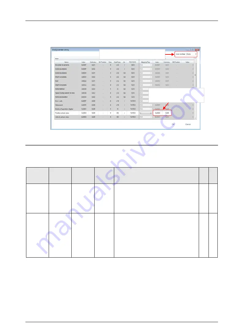
5. The "Used parameter setting" window is displayed. Set an index number for
the CoE object of the target slave device in "Position actual value (actual
position information area of motor)".
13.12.3
Monitor Operation
The input from the encoder can be counted. After that, it can be monitored by the AM current
value by requesting to turn on the servo of the axes for the encoder registered in FP7 MC Unit.
●: Available,
-: Not available
Axis no.
Unit
memory
no. (Hex)
Name
Default
Description
R
W
1
UM 02654
-UM 02655
AMP
current
value
(Absolute
coordinate)
K0
Stores the current value based on a mechanical
origin in pulse units. It will be reset to “0” on the
completion of home return. The value will not be
updated when the current value update function is
executed.
Unit: pulse
●
-
1
UM 02656
-UM 02657
Current
value after
unit
conversion
(Logic
system
coordinate)
K0
Stores the current value based on an electric
origin (value set as home position coordinate).
Stores values converted with the unit system
(pulse, μm, inch, degree) selected in the axis
parameter as integer. When the home return is
completed, the value set as home position
coordinate will be stored. When “0” is set as home
position coordinate, it will be reset to “0”. This area
is also updated when the current value update
function is used.
●
-
(Note): The count range of encoder input is unsigned 32 bits (0 to 4,294,967,295).
Set an index number for each counter
by switching the axis number.
Set the index number for the
CoE object of the counter
current value of the slave device.
Summary of Contents for AFP7MC16EC
Page 1: ......
Page 19: ...1 Unit Functions and Restrictions ...
Page 28: ...Unit Functions and Restrictions 1 10 ...
Page 29: ...2 Names and Functions of Parts ...
Page 33: ...3 Installation and Wiring ...
Page 47: ...4 Basic Procedure ...
Page 75: ...5 Settings of FP7 MC Unit Using CMI Tool ...
Page 97: ...6 Data Transfer to MC Unit and Test Operation ...
Page 122: ...Data Transfer to MC Unit and Test Operation 6 26 ...
Page 123: ...7 Creation of User Programs ...
Page 131: ...8 Automatic Operation Position Control ...
Page 143: ...8 2 Interpolation Control 8 13 ...
Page 193: ...9 Automatic Operation Synchronous Control ...
Page 251: ...10 Manual Operation JOG Operation ...
Page 257: ...10 2 Changing Speed During JOG Operation 10 7 MEMO ...
Page 263: ...11 Manual Operation Home Return ...
Page 277: ...12 Stop Functions ...
Page 286: ...Stop Functions 12 10 ...
Page 287: ...13 Supplementary Functions ...
Page 336: ...Supplementary Functions 13 50 ...
Page 337: ...14 CMTimeChart Monitor ...
Page 338: ...CMTimeChart Monitor 14 2 14 1 Overview of Function ...
Page 365: ...15 Troubleshooting ...
Page 396: ...Troubleshooting 15 32 ...
Page 397: ...16 Specifications ...
Page 500: ...Specifications 16 104 16 13Dimensions AFP7MC16EC AFP7MC32EC AFP7MC64EC 90 28 80 4 Unit mm ...
Page 502: ......
Page 503: ......
Page 504: ......


