9.6
Electronic Cam Function
9-53
9.6.5 Advance Angle Correction Function
What is advance angle correction function?
"Advance angle correction function" is a function to correct the delay in the response of a
machine system connected to an electronic cam output or the delay in a PLC arithmetic
processing time. This function is used to advance the input phase to electronic cams for
correcting the delay in the response of cam output axes.
The advance angle correction automatically increases a phase lead in proportion to the speed
of the master axis; therefore, it is also suitable for correcting deviation in proportion to the
speed. This function is available since FP7 MC Unit Ver. 1.20.
Specification of advance angle correction amount
Advance angle correction amounts are specified for each slave axis using a tool software or
user program.
By setting "advance angle correction reference speed" and "advance angle correction
reference amount", a correction amount is automatically calculated using an active "master
axis input speed". The advance angle correction amount is calculated by the following formula.
Advance angle
correction amount
Master axis input
speed information
Advance angle correction reference amount
[UM63F96-UM63F97]
Advance angle correction reference speed
[UM63F98-UM63F99]
* Master axis input speed information: Speed information after clutch control
=
×
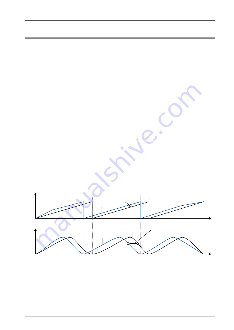
Internal processing of advance angle correction
The phase of the master axis which will be a reference of slave axis correction is obtained as
operation data for according to the set values of advance angle amount. A correction amount
for each slave axis is calculated based on this value as a reference.
t
t
Input axis phase
Output axis displacement
Not corrected
Advance angle
correction amount
Advance the output of slave axes!
Corrected
Not corrected
Corrected
Summary of Contents for AFP7MC16EC
Page 1: ......
Page 19: ...1 Unit Functions and Restrictions ...
Page 28: ...Unit Functions and Restrictions 1 10 ...
Page 29: ...2 Names and Functions of Parts ...
Page 33: ...3 Installation and Wiring ...
Page 47: ...4 Basic Procedure ...
Page 75: ...5 Settings of FP7 MC Unit Using CMI Tool ...
Page 97: ...6 Data Transfer to MC Unit and Test Operation ...
Page 122: ...Data Transfer to MC Unit and Test Operation 6 26 ...
Page 123: ...7 Creation of User Programs ...
Page 131: ...8 Automatic Operation Position Control ...
Page 143: ...8 2 Interpolation Control 8 13 ...
Page 193: ...9 Automatic Operation Synchronous Control ...
Page 251: ...10 Manual Operation JOG Operation ...
Page 257: ...10 2 Changing Speed During JOG Operation 10 7 MEMO ...
Page 263: ...11 Manual Operation Home Return ...
Page 277: ...12 Stop Functions ...
Page 286: ...Stop Functions 12 10 ...
Page 287: ...13 Supplementary Functions ...
Page 336: ...Supplementary Functions 13 50 ...
Page 337: ...14 CMTimeChart Monitor ...
Page 338: ...CMTimeChart Monitor 14 2 14 1 Overview of Function ...
Page 365: ...15 Troubleshooting ...
Page 396: ...Troubleshooting 15 32 ...
Page 397: ...16 Specifications ...
Page 500: ...Specifications 16 104 16 13Dimensions AFP7MC16EC AFP7MC32EC AFP7MC64EC 90 28 80 4 Unit mm ...
Page 502: ......
Page 503: ......
Page 504: ......


