background image

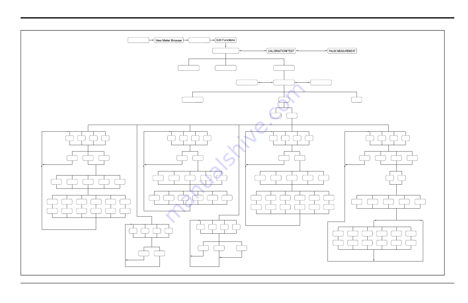
Appendix A. PanaView Menu Maps

DigitalFlow™ XMT868i Programming Manual

75

Input/Output

Comm Port

System

See Figure D-4

Error Handling

Options

Display

SLOT0

SLOT1

A

B

C

D

A

B

C

D

A

B

C

D

OFF

TTLZR

OFF

FREQ

LOW

FAULT

OFF

HIGH

CH1

CH2

+TOTL

–TOTL

+MASS

SUM

DIF

AVE

–MASS

+ENRG

–ENRG

Totalizer Outputs

Slot 1 Outputs

Channel 2-Channel meter)

Measurement Name

PULSE ON TIME

UNITS/PULSE

See Figure D-4

See Figure A-4

Slot 1

appears only if option card installed

(Option Card)

CH1

CH2

VEL

VOLUM

+TOTL

SUM

DIF

AVE

–TOTL

TIME

MDOT

Channel  2-Channel meter)

Measurement Name

(*all diagnostic

+MASS

–MASS

+ENRG

–ENRG

POWER

DIAG*

(appears only for

(appears only for

FULL SCALE FREQUENCY

BASE

FULL

parameters

Slot 1 Outputs

Frequency Outputs

NO

YES

CH1

CH2

VEL

VOLUM

+TOTL

SUM

DIF

AVE

–TOTL

TIME

MDOT

Channel  2-Channel meter)

 FAULT

(*all diagnostic parameters

+MASS

–MASS

+ENRG

–ENRG

POWER

DIAG*

(appears only for

Trigger point

appear here)

Failsafe?

HIGH/LOW

Slot 1 Outputs

Alarm Relays

appear here)

Measurement Name

A

B

C

D

OFF

0-20m

CH1

CH2

VEL

VOLUM

+TOTL

SUM

DIF

AVE

–TOTL

TIME

MDOT

Channel  2-Channel meter)

Measurement Name

(*all diagnostic

+MASS

–MASS

+ENRG

–ENRG

POWER

DIAG*

(appears only for

BASE

FULL

parameters

Slot 1 Outputs

Analog Outputs

appear here)

4-20m

A

B

C

D

OFF

TEMP

RTD Inputs

LABEL

Input Measurement

ZERO Value

FULL Scale Value

A

B

C

D

OFF

TEMP

Analog Inputs

LABEL

Input Measurement

FULL Scale Value

SPEC

INPUT NAME

BASE Value

INPUT UNITS

Channel 2*

Global

Channel 1

(* for 2-Channel meter only)

XMT868

FILE

SITE EDIT MENU

See Figures D-1, D-2 and D-3

See Figure D-4

See Figure D-4

Fi

gu

re

 5

7:

 G

LO

BA

L -

 I/

O

-O

PT

IO

N

SL

O

T1

 M

en

M

ap

Summary of Contents for DigitalFlow XMT868i

Page 1: ...panametrics com Flow 910 171P August 2021 DigitalFlow XMT868i Ultrasonic Flow Transmitter for Liquids 1 2 Channel Programming Manual...

Page 2: ......

Page 3: ...e registered trademarks of Baker Hughes Company and its subsidiaries in one or more countries All third party product and company names are trademarks of their respective holders DigitalFlow XMT868i U...

Page 4: ...ii no content intended for this page...

Page 5: ...t for each installation Auxiliary Equipment Local Safety Standards The user must make sure that he operates all auxiliary equipment in accordance with local codes standards regulations or laws applica...

Page 6: ...nd the environment In order to avoid the dissemination of those substances in our environment and to diminish the pressure on the natural resources we encourage you to use the appropriate take back sy...

Page 7: ...2 2 Programming the LCD 2 2 3 Displaying Data on a Computer Terminal 3 2 3 1 Preparing for PanaView Programming 3 2 3 2 The Text Display Output 4 2 3 3 The Graphing Output 6 2 3 4 Displaying Transduce...

Page 8: ...tem Option 29 C 5 3 Entering Pipe Parameters 33 C 5 4 Entering Input Output Parameters 38 C 5 5 Entering Setup Parameters 39 C 6 Entering Data in the Global Menu 44 C 7 Exiting the Site Edit Menu 64 C...

Page 9: ...GLOBL SYSTM enter the system units GLOBL I O set up error handling option cards and display GLOBL COMM set the serial port and MODBUS parameters As a programming aid a complete set of menu maps for t...

Page 10: ...ation of the Model XMT868i Failure to accurately enter all of the necessary information will result in unreliable flow data Therefore be sure to complete at least the sections of this chapter pertaini...

Page 11: ...the first digit of the bottom LCD line the previous parameter is displayed and can be edited When you power up the XMT868i the initial screen shows the model and software version The meter then start...

Page 12: ...sented for Channel 1 1 3 1 Selecting the Channel Measurement Method The ACTIV submenu permits selection of the desired measurement method 1 In the Keypad Program scroll to PROG and press Enter 2 In th...

Page 13: ...Totalizer Units for the totalized flow rate display listed in Table 2 and press Enter Table 1 Available Volumetric Units English Volumetric Units Metric Volumetric Units GAL S U S Gallons per Second...

Page 14: ...ogramming Manual for details or the Energy Option If you have activated Mass Flow continue to step 1 on the next page If you have activated the Energy Option but not Mass Flow skip to step 1 on page 7...

Page 15: ...ass Totals units for the totalized mass flow rate display listed in Table 3 and press Enter 5 Scroll to the desired number of Mass Decimal Digits digits to the right of the decimal point in the totali...

Page 16: ...point of RTN Return where the liquid exits or of SPPLY Supply where the liquid enters Scroll to the appropriate choice and press Enter You have completed entering data in the SYSTM option The meter re...

Page 17: ...nsducer proceed to the Pipe Material prompt in step 4 If you entered the number for a standard wetted transducer proceed to the Pipe OD prompt in step 5 If you entered the number for a special transdu...

Page 18: ...may also be obtained from standard pipe size tables found in Sound Speeds and Pipe Size Data 914 004 Table 6 Pipe Material Choices Material Types Steel Carbon Steel Stainless Steel Iron Ductile Iron...

Page 19: ...e ultrasonic signal Press Enter Note If a spoolpiece was ordered with the meter the transducer signal path length P and the transducer signal axial length L are engraved on the flowcell and or are inc...

Page 20: ...Note Some of the fluid types may require additional selections as shown in the following tables Table 8 Fluid Types for ENERGY OFF Tracking Windows NO Additional Selections YES Additional Selections...

Page 21: ...ccept the value for the Transducer Spacing by pressing Enter Note The XMT868i automatically calculates the transducer spacing You should not enter a different value unless specifically instructed by t...

Page 22: ...Enter The recommended setting is 0 1 ft sec 0 03 m sec Proceed with one of the following If the ENERGY OPTION is OFF the display now returns to the Channel menu If the ENERGY OPTION is ON refer to Te...

Page 23: ...ure input 6 One of the following two prompts will appear depending on your selection in Step 3 If Fixed was chosen enter the known fixed process temperature and press Enter The meter will only accept...

Page 24: ...w Limit value See Chapter 2 Error Codes in the Service Manual for a discussion of error codes 6 Press Enter to accept the current Vel High Limit value or enter a new value and press Enter The default...

Page 25: ...rsts are sent in one direction before sending in the other direction The default value for the above parameter is 8 and values of 2 4 8 16 and 32 are available 12 Press Enter to accept the current Err...

Page 26: ...peed enter a table of K factors based on velocity or reynolds number that compensates for non linear flow rates enable mass flow calculated for static fluid density select the size of the transducer t...

Page 27: ...type CstV velocity or CstR reynolds 4 Scroll to Yes to Edit the K factor Table or on No to retain the current K factor table and return to the ADVAN option and press Enter Note If the necessary veloc...

Page 28: ...tions AUTO The meter will automatically determine the code length short or long which is based on pipe size and transducer type SHORT is just few pulses with no code pattern built in In some cases the...

Page 29: ...serial communications port and MODBUS parameters To enter the GLOBL menu 1 From the display screen press Escape Enter Escape on the infrared keypad 2 Press Enter to enter the PROG menu 3 In the PROG...

Page 30: ...GAL M gallons minute L M Liter min GAL H gallons hour L H Liter hr MGD million gallons day ML D million liters day ft3 s Cubic ft sec m 3 s Cubic m sec ft3 m Cubic ft min m 3 m Cubic m min ft3 h Cubic...

Page 31: ...ramming Manual for details or the Energy Option in one of the Channel PROGRAM options If you have activated Mass Flow continue to step 1 on the next page If you have activated the Energy Option but no...

Page 32: ...units for the totalized mass flow rate display listed in Table 12 and press Enter 5 Scroll to the desired number of Mass Decimal Digits digits to the right of the decimal point in the totalized mass...

Page 33: ...selections in this option The program returns to the Global PROGRAM menu Table 13 Available Power Units English Metric kBTUh Thousands of BTUs hour kCALs Kilocalories second MMBTU Mega BTUs hour kCAL...

Page 34: ...ring an error condition See Chapter 2 Error Codes in the Service Manual for a discussion of the built in error codes 1 In the Global I O option scroll to ERROR and press Enter 2 Scroll to the desired...

Page 35: ...returns to the Global I O option Table 16 Error Options and Responses for a 2 Channel Meter When Measuring Display Response Totalizer Response When Error Handling is HOLD LOW HIGH HHIGH CH1 or CH2 vel...

Page 36: ...n for programming instructions specific to the type of input or output selected above Analog Outputs Complete the following steps to set up the analog outputs for any slot refer to Figure 31 on page 1...

Page 37: ...signals REYN Current velocity reynolds number K RE K factor based on the Reynolds number PEAK Percentage of peak set to 50 by default THETA3 Theta 3 is the angle between the ultrasonic beam and the no...

Page 38: ...press Enter 6 Enter a measurement value for the Full high end of the analog output range and press Enter After responding to the above prompt the meter returns to the I O option DENSr Displays the de...

Page 39: ...another input or press Escape to move to another menu TEMP If TEMP was selected to set up input A as a live temperature input complete steps 4 and 5 below 4 Enter a temperature value for the Base low...

Page 40: ...s used here as an example Identical procedures would be used to set up the remaining RTD inputs 2 Enter a Label of up to eight characters for Input A and press Enter 3 Scroll to Off to disable Input A...

Page 41: ...of the Startup Guide for failsafe wiring instructions For a 1 Channel meter proceed to step 5 4 Scroll to the desired Channel option and press Enter See Table 20 for a description of the channel optio...

Page 42: ...ip to step 4 3 Scroll to the desired Channel option and press Enter See Table 20 on page 33 for a description of the channel options available at the above prompt 4 Scroll to the desired Measurement N...

Page 43: ...on page 33 for a description of the channel options available at the above prompt 4 Scroll to the desired Measurement Name Table 19 on page 29 provides a description of the available parameters Note T...

Page 44: ...following the programming instructions refer to Figure 31 on page 10 1 4 3 1 Setting Up the Serial Port 1 To enter this submenu from the Global PROGRAM menu scroll to COMM and press Enter 2 Enter a Me...

Page 45: ...turned data types is Integer 16 bit Integer MSB LSB 1 Register 16 bit integer Integer 32 bit IntegerI MSB LSB LSB LSB 2 Register 32 bit integer Floating Point FP EXP MAN MAN MAN 2 Registers 32 bit IEE...

Page 46: ...ss supplied as part of customer documentation The default TCP Port is 502 The default IP addressing for the XMT868i is DHCP dynamic If you need to assign a static IP address to the XMT868i complete th...

Page 47: ...1 4 32 bit integer 18 CH 1 SNDSP ft s or m s 0 4 32 bit integer 20 CH 2 Velocity ft s or m s 2 4 32 bit integer 22 CH 2 Volumetric VOL_U 4 IEEE 32 bit 24 CH 2 Totals TOT_U Register 28 4 32 bit intege...

Page 48: ...integer 75 CH 2 Energy Energy_u Register 77 4 32 bit integer 77 CH 2 Energy Digits none 0 2 16 bit integer 78 CH 2 TempS F or C 2 4 32 bit integer 80 CH 2 TempR F or C 2 4 32 bit integer 82 CH 2 TS T...

Page 49: ...te 5 2400 6 4800 7 9600 6 MODBUS parity 0 none 1 odd 2 even 7 MODBUS stop bits 1 1 stop bit 2 2 stop bits 8 General Registers are written if corresponding functions are actuated by the user Registers...

Page 50: ...Chapter 1 Programming Site Data 42 DigitalFlow XMT868i Programming Manual...

Page 51: ...in sequence In addition the contrast of the LCD may be adjusted for optimum viewing Proceed to the appropriate section for instructions 2 2 1 Adjusting LCD Contrast The LCD contrast may be adjusted t...

Page 52: ...keys until you have reached the desired option For a 1 Channel XMT868i the data for Channel 1 is displayed automatically and you can skip to step 9 However for a 2 Channel meter the channel data to be...

Page 53: ...e document EIA RS Serial Communications 916 054 You must also install PanaView as discussed in the PanaView User s Manual 910 211 and in Appendix C Programming the XMT868i Using PanaView 1 Power up th...

Page 54: ...ctual data values can be displayed in the text pane activate one of the following data collection modes see Figure 3 on page 4 Click on the Get Once option button at the bottom of the right pane in th...

Page 55: ...indows application the multiple text screens may be resized by dragging their borders Also the individual panes within a parameter s text screen may be resized by dragging the borders within that text...

Page 56: ...ument and display it graphically in a new format complete the following steps 2 3 3 1 Setting Up a Graph 1 Perform Steps 1 3 on page 3 2 Pull down the Output menu and click on the Graphing New option...

Page 57: ...ed for any other active meter channels 3 To begin plotting data for the selected parameter s enter a time Interval for data sampling in the text box provided the default value is 5 seconds 4 Click on...

Page 58: ...s XMT868i users to read and plot transducer signals from the XMT868i 1 From the New Meter Browser highlight the XMT868i 2 Right click on the highlighted XMT868i and click on the Properties option as s...

Page 59: ...down menu and click on the desired channel After a moment the Properties window appears similar to Figure 7 Figure 7 Active Signal Options 4 To select a different signal type open the signal menu at t...

Page 60: ...Flow XMT868i Programming Manual 2 3 4 3 Saving Transducer Signals To save the raw signal click on Save A window opens similar to Figure 9 Enter the desired name and click on Save to save the signal as...

Page 61: ...age on the PC s hard drive This chapter explains how to use the Model XMT868i s data logging capability with PanaView 3 2 The Data Logging Option Card In order to log data the Model XMT868i must be fi...

Page 62: ...in PanaView expand the network tree and open the Edit Functions option described on page C 6 of Appendix C Programming the XMT868i Using PanaView The menu will appear similar to Figure 10 Figure 10 E...

Page 63: ...r of Variables you wish to log Type in the desired number from 1 to 6 and click Next Item f Double click on the desired Channel for the first variable g Scroll to and double click on the desired Measu...

Page 64: ...umber in the right window and click Next Item or simply click Next Item to step through the parameters If you select Timed PanaView asks for the Log Time duration Scroll to and double click on the des...

Page 65: ...right window or scroll to and click on the desired month and click Next Item or simply click Next Item to step through the parameters Note If you have selected a circular log PanaView now indicates t...

Page 66: ...in the last section To create a new PC log 1 Open the Output menu see Figure 13 and click on the Logging option Figure 13 Selections in the Logging Option You have two choices Click on the New PC Log...

Page 67: ...a PC Log 4 At the dialog box shown in Figure 16 click on the Create option button to create a new meter log 5 Enter a log file name Sample in this case in the dialog box shown in Figure 17 Click on t...

Page 68: ...s they are selected the parameters are listed in the lower right pane of the PC Log window make sure that the Log Items tab in this pane is selected Note To add all the channel parameters to a given l...

Page 69: ...ing Click on the Contents tab see Figure 21 on page 10 for a list of all the data points logged to date for the parameter currently highlighted on the Log Items tab Click on the Graph option button to...

Page 70: ...Chapter 3 Logging Data 10 DigitalFlow XMT868i Programming Manual Figure 21 Typical Log Contents...

Page 71: ...Figure 23 Selecting a Log File from the Log Browser Notice that each of the log files in Figure 22 and Figure 23 has a traffic light icon next to its name These icons indicate the current status of th...

Page 72: ...mation shown on the Contents tab and in the Graph Log window Any data logged since the last use of the Refresh option button is added to the list and to the graph Remember that only two parameters per...

Page 73: ...al PanaView software Note See Chapter 1 Installation of the Startup Guide for instructions on wiring the RS232 serial port For additional information refer to the EIA RS Serial Communications Manual 9...

Page 74: ...Chapter 4 Printing Data 2 DigitalFlow XMT868i Programming Manual...

Page 75: ...ted option are thoroughly understood before proceeding 5 2 Clearing the XMT868i s Memory If the XMT868i s available memory becomes nearly full it may be necessary to purge some or all of the existing...

Page 76: ...e Log Browser option as shown in Figure 24 Figure 24 Log Browser in the Logging Option 2 Double click on the computer name to move to the network level 3 Double click on PC Logs to access the stored P...

Page 77: ...Totals Scroll to NO or YES 2 and press Enter at the desired choice The XMT868i totalizers are reset to 0 and the meter returns to the Keypad Program Press Escape to return to the data display To rese...

Page 78: ...Chapter 5 Clearing Data 4 DigitalFlow XMT868i Programming Manual...

Page 79: ...DigitalFlow XMT868i Programming Manual 5 Appendix A Menu Maps Appendix A Menu Maps...

Page 80: ...Appendix A Menu Maps 6 DigitalFlow XMT868i Programming Manual...

Page 81: ...DECIMAL DIGITS Metric English KG TONNES MASS DECIMAL DIGITS 0 1 2 3 MASS TOTALS MASS FLOW LB KLB MMLB TONS MASS FLOW ON MASS FLOW OFF KBTU MMBTU kW TONS Kcal Mcal KWHr MWHr Metric English POWER 0 1 2...

Page 82: ...ERIAL LINING SOUNDSPEED LINING THICKNESS YES NO TRACKING WINDOWS WATER MIXED OTHER WATER TEMPERATURE FLUID SOUNDSPEED FLUID SOUNDSPEED Percentage of Water W260 MIXED OTHER MINIMUM SOUNDSPEED Percentag...

Page 83: ...LOW LIMIT 4 2 8 16 32 XMIT SAMPLE SIZE See Figure A 2 SIGNL AVRG INIT ADVAN 10 5 30 2 1 STATS 60 RESPONSE TIME Max Peak Min Peak of Errors NO YES NO YES AUTO SHORT CstV CstR MULTK MASS CODEL KV xx NO...

Page 84: ...OPTION OFF ENERGY OPTION ON ENERGY OPTION OFF ENERGY DECIMAL DIGITS Liter S Liter M Liter H m3 h Mm3 d BBL S MLiter D m3 s m3 m BBL M BBL H MBL D 2 CHANNEL UNITS 1 CHANNEL UNITS See Figures A 1 A 2 a...

Page 85: ...ENRG POWER DIAG appears only for appears only for FULL SCALE FREQUENCY BASE FULL parameters Slot 1 Outputs Frequency Outputs NO YES CH1 CH2 VEL VOLUM TOTL SUM DIF AVE TOTL TIME MDOT Channel 2 Channel...

Page 86: ...Appendix A Menu Maps DigitalFlow XMT868i Programming Manual...

Page 87: ...2 Current Inputs 2 Totalizer Inputs 1473 05 TR 2 RTD Inputs 2 Totalizer Inputs 1473 06 FI 2 Current Inputs 2 Frequency Inputs 1473 07 FR 2 RTD Inputs 2 Frequency Inputs 1473 08 AI 2 Current Inputs 2...

Page 88: ...ed Whenever an option card is installed or changed in the XMT868i flow transmitter record the type of card and any additional setup information in the appropriate row of Table 24 Table 24 Option Cards...

Page 89: ...Bits MOD Baud Rate MOD Address Channel x ACTIV Channel 1 Channel 2 if applicable Channel Status Off1 Trans Channel Status Off1 Trans Channel x SYSTEM Channel 1 Channel 2 if applicable Channel Label Ch...

Page 90: ...Pipe Wall Pipe Wall Path Length P Path Length P Axial Length L Axial Length L Trans Angle Trans Angle Lining Yes No Lining Yes No Lining Material Lining Material Lining Sndspd Lining Sndspd Lining Thi...

Page 91: ...20 Channel x SETUP ADVANCED FEATURES MULTIK Custom Type CstV CstR Custom Type CstV CstR K Factor Table K Factor Table K Factor Vel Reyn K Factor K Factor Vel Reyn K Factor 1 1 2 2 3 3 4 4 5 5 6 6 7 7...

Page 92: ...lFlow XMT868i Programming Manual 18 18 19 19 20 20 CHx SETUP ADVAN MASS Mass Flow No Yes Mass Flow No Yes Static Density Static Density CHx SETUP ADVAN CODEL Code Length Auto Short Long Code Length Au...

Page 93: ...et the signal limits response times and activating mass flow Global System enter the system units Global I O set up error handling option cards and display Global Comm set the serial port and MODBUS p...

Page 94: ...ser window in the File menu and expand the network tree Then highlight the My Com puter Name branch by clicking on it 3 Pull down the Edit menu by clicking on it in the menu bar 4 Click on the New men...

Page 95: ...tting up Ethernet Communications If you have selected TCP IP in step 6 on the previous page the Setup Communications window appears similar to Figure 35 Figure 35 Setup Communications for TCP IP 1 Typ...

Page 96: ...eed to assign a static IP address to the XMT868i complete the following steps IMPORTANT To assign a static IP address the XMT868i must be connected to an Ethernet network with a dynamic address assign...

Page 97: ...on it and then open the Edit menu on the menu bar if the communication port is not highlighted first the New Meter option is not active in the Edit menu 2 Click on the New option in the Edit menu see...

Page 98: ...zation is successful the Meter Browser shows a listing similar to Figure 38 Figure 38 The Updated Network Tree However if the settings do not match or there is some other difficulty a screen appears s...

Page 99: ...complete at least the sections of this chapter pertaining to those three submenus Except for those three submenus it is not necessary to program the Model XMT868i flowmeter in any particular order Th...

Page 100: ...hannel 1 Channel 2 or Global highlight and double click on the desired menu in the left pane For example clicking on Channel 1 in Figure 42 opens the list of options shown in the center pane 5 To ente...

Page 101: ...rough the menu the bottom panel lists the current settings you have modified or left unchanged as shown in Figure 44 If you modify or step through more than five items a scroll bar at the right of the...

Page 102: ...will be described To program Channel 2 of a 2 Channel meter simply repeat the same procedures presented for Channel 1 C 5 1 Selecting the Channel Measurement Method The Status submenu permits selectio...

Page 103: ...from the list shown in Table 26 and double click on the desired units Note Refer to the System option of the Global menu to choose between English or metric measurements Table 26 Available Volumetric...

Page 104: ...program now varies depending on whether you have activated MASS FLOW see the Programming Manual for details or the ENERGY OPTION If you have activated MASS FLOW continue to step 1 on the next page If...

Page 105: ...Units for the totalized mass flow rate display listed in Table 28 5 Double click on the desired number of Mass Decimal Digits digits to the right of the decimal point in the total ized mass flow rate...

Page 106: ...ck on the appropriate choice You have completed entering data in the System option PanaView returns to the Channel PROGRAM menu shown in Figure 42 on page 26 Proceed to the next page to enter Pipe par...

Page 107: ...a standard wetted transducer proceed to the Pipe OD prompt in step 5 If you entered the number for a special transducer proceed to step 3 below C 5 3 1 Special Transducers 3 For special transducers a...

Page 108: ...tainless Steel Iron Ductile Iron Cast Iron Copper no additional selection required Aluminum no additional selection required Brass no additional selection required Copper Nickel 70 Cu 30 Ni 70 30 Copp...

Page 109: ...length P and the transducer signal axial length L are engraved on the flowcell and or are included in the documentation supplied with the meter For on site transducer installations refer to Appendix...

Page 110: ...tions required Methanol 25 C No additional selections required Oil No additional selections required Ethanol 25C No additional selections required OTHER Enter the Minimum Soundspeed and click on Next...

Page 111: ...If one of the table options is selected enter the Calibration Factor and click on Next Item If Static is selected enter the Kinematic Viscosity and click Next Item Then enter the Calibration Factor a...

Page 112: ...display now returns to the Channel menu If the ENERGY OPTION is ON refer to Temperature Input below C 5 4 2 Temperature Input The Model XMT868i can use either a fixed temperature value or a live tempe...

Page 113: ...s Consult the factory before changing any of these parameters 1 From the Set Up option menu highlight and double click on Signal in the center pane 2 Click Next Item to accept the current Signal Low L...

Page 114: ...m An offset between the upstream and downstream transit times is specified at this prompt The default value for the above parameter is 0 sec and values from 1000 to 1000 sec are acceptable 11 Click Ne...

Page 115: ...an do the following calculate the kinematic viscosity KV based on signal strength SS or soundspeed C3 enter a table of K factors based on velocity or reynolds number that compensates for non linear fl...

Page 116: ...lick on the desired Custom Type velocity or reynolds 4 Double click on Yes to Edit the K factor Table or on No to retain the current K factor table and return to the Advanced Features window Note If t...

Page 117: ...lowing selections AUTOMATIC The meter will automatically determine the code length short or long which is based on pipe size and transducer type SHORT CODE is just few pulses with no code pattern buil...

Page 118: ...e SUM DIF or AVE readouts data from the Global System submenu is used Any conflicting data entered in the Channel System submenu is overridden The following submenus are included in the Global menu Sy...

Page 119: ...e window now appears similar to Figure 46 Figure 46 The System Option in the Global Menu 3 The first prompt asks for a Meter Message Enter a numeric or text message up to 16 characters in the right pa...

Page 120: ...ish Metric Gal sec gallons second Liter sec Gal min gallons minute Liter min Gal hr gallons hour Liter hr MegaGal day million gallons day MegaLiter day million liters day Cubic ft sec Cubic m sec Cubi...

Page 121: ...ual for details or the Energy Option in one of the Channel PROGRAM options If you have activated Mass Flow continue to step 1 on the next page If you have activated the Energy Option but not Mass Flow...

Page 122: ...otals units for the totalized mass flow rate display listed in Table 37 5 Double click on the desired number of Mass Decimal Digits digits to the right of the decimal point in the total ized mass flow...

Page 123: ...ons in this option The program returns to the Global PROGRAM menu Table 38 Available Power Units English Metric kBTU h Thousand BTUs hour kCALs Kilocalories second MMBTU Mega BTUs hour kCALm Kilocalor...

Page 124: ...See Chapter 2 Error Codes in the Service Manual for a discussion of the built in error codes 1 From the Input Output option highlight and double click on the Error Handling option in the center pane...

Page 125: ...Output option menu Table 41 Error Options and Responses 2 Channel Meter When Measuring Display Response Totalizer Response When Error Handling is HOLD LOW HIGH HHIGH CH1 or CH2 vel vol etc Holds last...

Page 126: ...e prompt Proceed to the appropriate section for programming instructions specific to the type of input or output selected above Analog Outputs Complete the following steps to set up the analog outputs...

Page 127: ...eta 3 Theta 3 is the angle between the ultrasonic beam and the normal to the pipe wall It is calculated from the measured transit time and clamp on parameters clamp ons only UP Signal Q Displays the s...

Page 128: ...in the Global System menu earlier in this section 5 Enter a flow rate value for the Base low end of the analog output range and click on Next Item 6 Enter a flow rate value for the Full high end of t...

Page 129: ...age to move to another menu TEMP If TEMP was selected to set up input A as a live temperature input complete steps 4 and 5 below 4 Enter a value for the Base low end of the analog input range and clic...

Page 130: ...ed here as an example Identical procedures would be used to set up the remaining RTD inputs 2 Enter a Label of up to eight characters for input A and click on Next Item 3 Double click on Off to disabl...

Page 131: ...nstructions For a 1 Channel meter proceed to step 5 4 Double click on the desired Channel option See Table 45 for a description of the channel options available Note If FAULT was selected as the alarm...

Page 132: ...eter skip to step 4 3 Double click on the desired Channel option See Table 45 on page 57 for a description of the channel options available at the above prompt 4 Double click on the desired Measuremen...

Page 133: ...ed Channel option See Table 45 on page 57 for a description of the channel options available at the above prompt 4 Double click on the desired Measurement Name Table 44 on page 53 provides a descripti...

Page 134: ...e desired option For a 1 Channel XMT868i the data for Channel 1 is displayed automatically and you can skip to step 4 However for a 2 Channel meter the channel data to be displayed must be specified a...

Page 135: ...l for more information IMPORTANT If the meter address or baud rate is changed communication with PanaView must be re established with the new address number 3 Double click on the desired Baud Rate fro...

Page 136: ...SUP none 1 4 32 bit integer 16 CH 1 SSDN none 1 4 32 bit integer 18 CH 1 SNDSP ft s or m s 0 4 32 bit integer 20 CH 2 Velocity ft s or m s 2 4 32 bit integer 22 CH 2 Volumetric VOL_U 4 IEEE 32 bit 24...

Page 137: ...initialized to zero at startup 58 CH 1 Energy Energy_u Register 62 4 32 bit integer 60 CH 1 Energy Energy_u Register 62 4 32 bit integer 62 CH 1 Energy Digits none 0 2 16 bit integer 63 CH 1 TempS F o...

Page 138: ...ng the Global submenu PanaView returns to the Site Edit Menu Click Close to exit the Site Edit Menu Then proceed to Chapter 3 Operation of the Startup Guide for instructions on taking measurements or...

Page 139: ...file data in a PC and reload it into the XMT868i To save or reload site data using PanaView 1 In the New Meter Browser highlight the XMT868i 2 Right click on the highlighted XMT868i and select the Pr...

Page 140: ...ent Site Data to the Meter To save existing site data to the meter 1 Select the radio button for Selected and highlight an existing site in the left pane 2 Then click on the Save Site to Meter button...

Page 141: ...s Highlight a site file with the desired settings and click Open The site file becomes the Working site in the meter with the desired settings C 8 3 Saving a Site to the PC To save a site to the PC 1...

Page 142: ...e XMT868i on the previous page C 8 4 Saving Site Data in Text Form To store the data from a site file as a text file for display or printout 1 Highlight the site in the left pane See Figure 49 on page...

Page 143: ...DigitalFlow XMT868i Programming Manual 69 Appendix D PanaView Menu Maps for the XMT868i Appendix D PanaView Menu Maps for the XMT868i...

Page 144: ...Appendix D PanaView Menu Maps for the XMT868i 70 DigitalFlow XMT868i Programming Manual...

Page 145: ...2 3 MDOT DECIMAL DIGITS Metric English KG TONNES MASS DECIMAL DIGITS 0 1 2 3 MASS TOTALS MASS FLOW LB KLB MMLB TONS Mass Flow On Mass Flow Off KBTUh MMBTU kW TONS Kcal Mcal KWHr MWHr Metric English PO...

Page 146: ...tage of Water W260 MIXED OTHER MINIMUM SOUNDSPEED Percentage of Water MAXIMUM SOUNDSPEED OFF ACTIVE TABLE STATIC TABLE KV INPUT SELECTION KINEMATIC VISCOSITY REYNOLDS CORRECTION CALIBRATION FACTOR Wet...

Page 147: ...xx Table NO YES Long Code Activate Multi K Fact Custom Type Edit Table Enter of K Factors Reynolds Velocity K Factor Repeat for the of K Factors entered previously Mass from Static Dens Fluid Density...

Page 148: ...AL DIGITS Liter S Liter M Liter H m3 h Mm3 d BBL S MLiter D m3 s m3 m BBL M BBL H MBL D 2 CHANNEL UNITS 1 CHANNEL UNITS Options Display YES NO Error Handling 2PATH ERROR HANDLING SLOT0 OFF 0 20m 4 20m...

Page 149: ...quency Outputs NO YES CH1 CH2 VEL VOLUM TOTL SUM DIF AVE TOTL TIME MDOT Channel 2 Channel meter FAULT all diagnostic parameters MASS MASS ENRG ENRG POWER DIAG appears only for Trigger point appear her...

Page 150: ...Appendix A PanaView Menu Maps DigitalFlow XMT868i Programming Manual 76...

Page 151: ...e seconds Ch2 Totalizer Time seconds Avg Totalizer Time seconds Ch1 Error Value none Ch2 Error Value none Avg Error Value none Ch1 SSUP none Ch2 SSUP none Avg SSUP none Ch1 SSDN none Ch2 SSDN none Avg...

Page 152: ...asurement unit for each AI 1 Double click on the FLOW Transducer Block in the tree under GEFlow XMT 2 Select the Others tab and open the drop down list for the PRIMARY_SELECTOR and SECONDARY_SELECTOR...

Page 153: ...click on the AI block for which you wish to set the units ANALOG_INPUT_1 or ANALOG_INPUT_2 in the tree under Panametric Flow XMT see Figure 58 on page 78 2 Select the Scaling tab and set the unit for...

Page 154: ...Appendix E Foundation Fieldbus Communications 80 DigitalFlow XMT868i Programming Manual Figure 60 Units Index Drop Down List...

Page 155: ...click on the FLOW transducer block in the tree under GEFlow XMT see Figure 58 on page 78 2 Select the Others tab and scroll down to the CLEAR_TOTALIZERS listing 3 Select Clear from the drop down list...

Page 156: ...up using the Function Block Application editor The flowmeter AI blocks along with the AO and PID of another device on the network are displayed We have connected the AI_1 OUT of the flowmeter to the C...

Page 157: ...Communications Setting Up 36 Corr Peak Limit 16 39 D Data Displaying Using PanaView 3 4 Default Setup Option 18 41 Default Setup Submenu Advanced Features Option 41 Delta T Offset 16 40 Displaying Dat...

Page 158: ...0 GLOBL SYSTM 10 Menus Edit 20 Output 3 Meter Address Number 36 Meter Logs Creating 2 Meter Message 21 Min Peak Limit 17 Minimum Percent of Peak 40 MODBUS 61 MODBUS Communications Setting Up 37 MODBUS...

Page 159: ...atus of Logs 11 Status Submenu 4 28 System Channel Submenu 5 System Global Submenu 21 45 System Units in Global Menu PanaView 45 in GLOBL Menu 21 T Temperature Input Entering 14 38 Text Window 4 Time...

Page 160: ...Index 4 DigitalFlow XMT868i Programming Manual X Xmit Code Length 20 XMIT Sample Size 17 40 Z Zero Cutoff Value Entering 14 in PanaView 38...

Page 161: ...purpose and warranties arising from course of dealing or usage or trade Return Policy If a Panametrics Sensing instrument malfunctions within the warranty period the following procedure must be compl...

Page 162: ...Warranty 6 AquaTrans AT868 User s Manual no content intended for this page...

Page 163: ......

Page 164: ...and company names are trademarks of their respective holders 910 171P Rev F Customer Support Centers U S A The Boston Center 1100 Technology Park Drive Billerica MA 01821 U S A Tel 800 833 9438 toll...

Reviews: