ILK
22/33/44/55/66
I
NSTALLATION
M
ANUAL
Revision 1.6
- 16 -
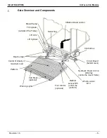
Gate and Platform Installation
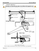
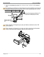
Refer to 4.1 for flip-up door/full seal kit and swing door applications BEFORE INSTALLATION
Refer to 5.2 for installs with Mounting Fixture BEFORE INSTALLATION
5.1
Sill Preparation
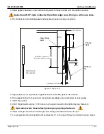
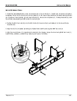
1. Reinforce back sill by welding a ½
” flat bar to the rear, 8 welds each on top and bottom.
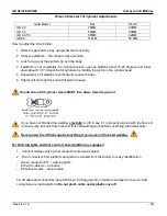
2. Notch rear sill, if necessary, per installation table (Section 3.1) for your particular model.
3. Box in notch with flat bar to maintain sill strength.
5.2
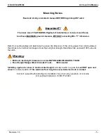
Installation with mounting fixture
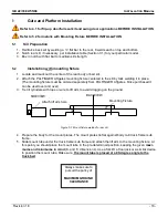
1. Locate and mark out the center of the rear body or bed sill.
2. Attach the PALFINGER Liftgates
mounting fixture centered to the sill by tack welding it in place.
(The mounting fixture must be ordered separately from PALFINGER Liftgates. Once purchased it
can be used over and over)
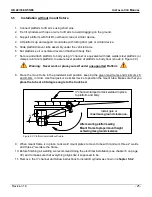
3. Tie tilt cylinders with rope or wire to lift arm to avoid dragging on the ground
Figure 5.1: Mount fixture welded to rear sill
4. Prepare the body for the mount plates. The mount plates lie flat against body rail/ truck frame/ sub
frame.
5. Slide mount tube under the truck frame/ sub frame and attach the lift arm to the mounting fixture. At
this point you should place the mount tube in the pre-determined position, keeping the given
maxi-
mums and minimums in mind
(K- and F- dimensions). Use a forklift, a floor jack or a similar device
to position the mount tube. Make sure
the mount tube is placed at a 90-degree angle to the
truck bed
.
Attach lift arm here
Always make sure to
pursuit the policy of
MAXIMUM GROUND
CLEARANCE
BACKVIEW
Mounting
Fixture
SIDEVIEW

