


51
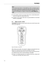
8.6. Connecting the manual cable switch (optional)
A manual cable switch or a radio remote control are optionally available for
your
PALFINGER Tail Lifts
tail lift.
Note:
When installing a manual cable switch, you must attach the cable with
socket under the vehicle loading area so that the cable can be connected
to the manual cable switch.
Figure 28: Manual cable switch
Lead
Pin
Leads manual cable switch
for three buttons
for two buttons
1
4
white
-
2
5
green
-
3
6
black
yellow
4
3
yellow
red
ye/gn
2
red
green/black
►
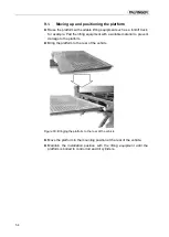
Select a suitable place for mounting the socket under the vehicle loading
bay. A fixing option is provided on most control panel holders.
►
Mount the socket.
►
Connect the cable from the socket in the terminal box in accordance with
the
PALFINGER Tail Lifts
circuit diagram.
Cores
Plug