50/172
cod. 00 477 2250 - 11/2013 - PN - Italy
INSTALLATION
6.6.3 Starting
To start, press the switch down, “I”, (On) (Fig. 6.6.5).
6.6.4 External connections
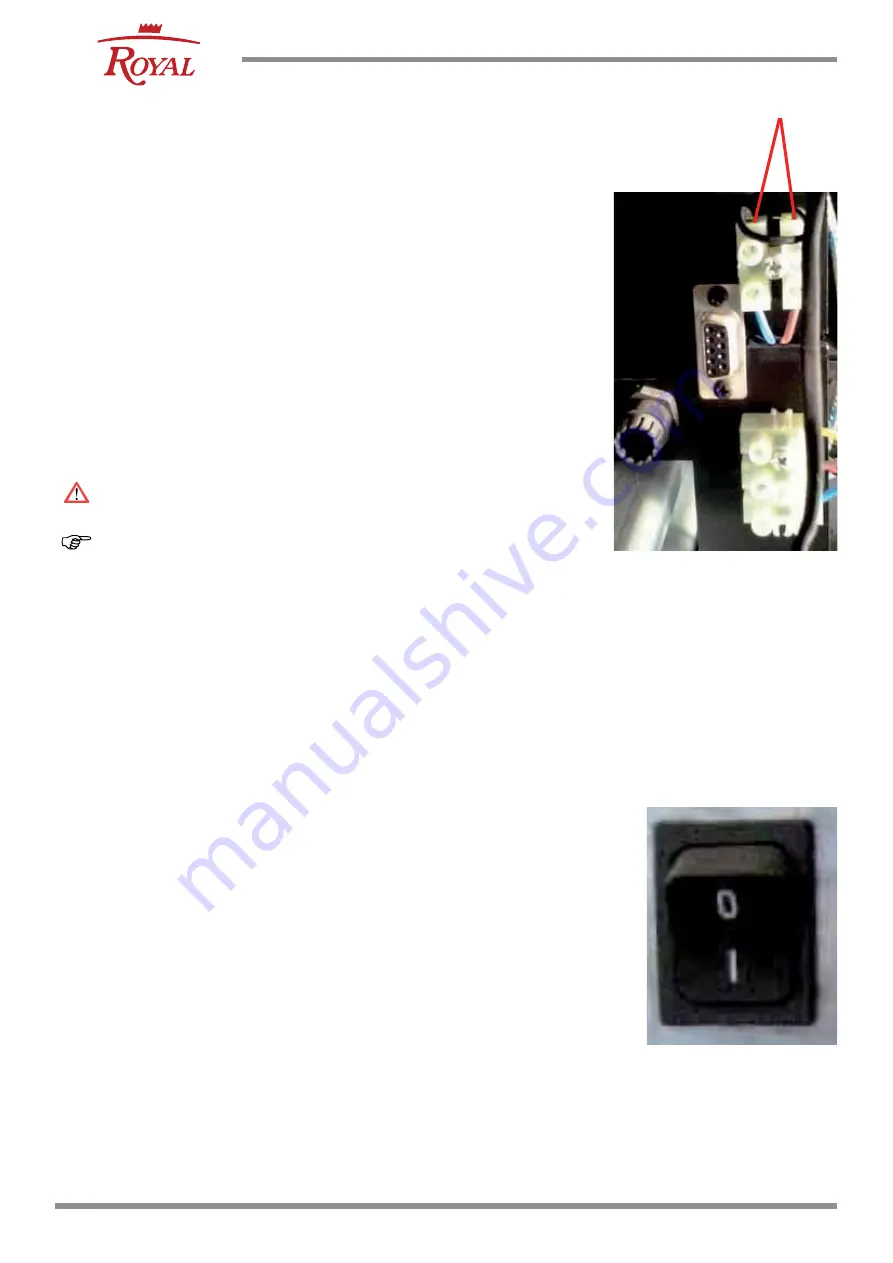
Where available, on the upright of the stove are
installed (Fig. 6.6.4):
TA =Room thermostat
RS232 =Royal serial connection for internal use
6.6.5 Thermostat connection
THERMOSTAT CONNECTION TERMINAL
BLOCK (Fig. 6.6.4)
If a thermostat (TA) is used it has to be connected to
the terminal block at the back of the stove, following
the diagram given in Fig. 6.6.4.
Room thermostat (N.C.= Normally closed)
If the board is connected to a room thermostat
whose contact opens upon reaching room
level (minimum operating level) while keeping the
standard functioning unchanged.
Disconnect the mains power supply before
proceeding with connections.
The room thermostat must be the free contact type.
(There must be no output voltage).
6.6.6 External Water Probe Connection (SA)
The fireplace is set up for connection with an
external water probe .
The puffer sensor must be activated by the technical
service centre.
Fig. 6.6.4
Fig. 6.6.5
TA


