


PALAS GmbH
Partikel- und Lasermesstechnik
Greschbachstrasse 3b
76229 Karlsruhe
Phone +49 (0)721 96213-0
Fax +49 (0)721 96213-33
[email protected]
www.palas.de
Operating Manual
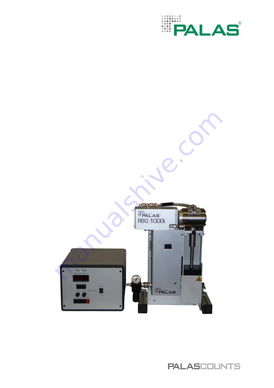
Solid Particle Disperser
S e r i e s o f R B G 1 0 0 0 I
PALAS GmbH
Partikel- und Lasermesstechnik
Greschbachstrasse 3b
76229 Karlsruhe
Phone +49 (0)721 96213-0
Fax +49 (0)721 96213-33
[email protected]
www.palas.de
Operating Manual
Solid Particle Disperser
S e r i e s o f R B G 1 0 0 0 I