H
I
G
AIN
L
INE
U
NIT
Q
UICK
I
NSTALLATION
G
UIDE
P
AIR
G
AIN
T
ECHNOLOGIES
, I
NC
.
S
ECTION
350-231-174-01
Revision History of this guide.
Revision 01—December 10, 1997
A) Initial Release
Model
List
Part Number
CLEI Code
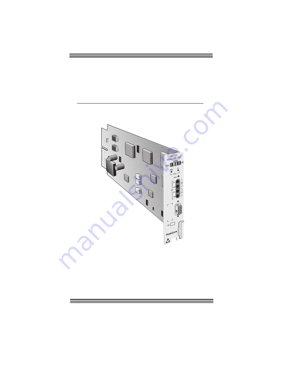
HLU-231
7D
150-1111-74
T1LI4144AA


