background image


6


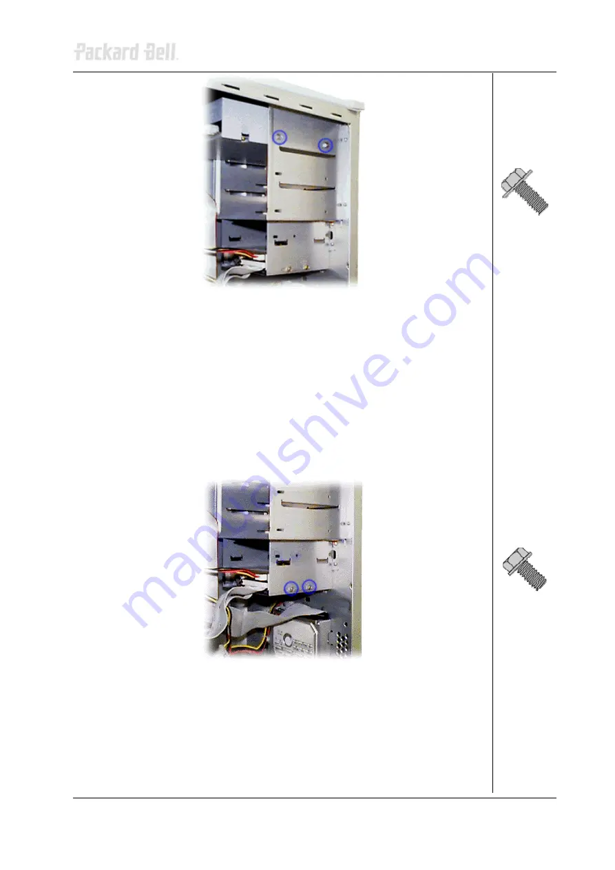
Fig. 5:  

Removing the DVD/CD-ROM drive screws 


3.  Slide the drive towards the front out of the bay. 


Removing the Floppy Disk Drive 

To remove the floppy disk drive, first remove the front bezel (see section 

Removing the 

Front Bezel

), remove the left side cover (see section 

Removing the Left Side Cover

), 

remove the right side cover (see section 

Removing the Right Side Cover

); then follow the 

steps below: 
 

1.  Disconnect all cables from the 3.5-inch floppy disk drive. 
2.  Remove the screws holding the floppy disk drive in the bay. 


Fig. 6:  

Removing the floppy disk drive screws 

3.  Slide the floppy disk drive towards the front out of the bay. 


Removing the Hard Disk Drive 

To remove the hard disk drive, first remove the front bezel (see section 

Removing the Front 

Bezel

) and remove the left side cover (see section 

Removing the Left Side Cover

); then 

follow the steps below: 


Packard Bell Daytona Disassembly Manual 

Summary of Contents for Daytona

Page 1: ...Packard Bell Daytona Disassembly Manual ...

Page 2: ... Power Supply Unit 3 Removing the Front Bezel 4 Removing the Left Side Cover 4 Removing the Right Side Cover 4 Removing the DVD CD ROM Drive 5 Removing the Floppy Disk Drive 6 Removing the Hard Disk Drive 6 Removing Add In Cards 7 Removing the Front USB Port 7 Removing the Switch LED Assembly 8 Removing the Power Supply 9 Notice 10 Packard Bell Daytona Disassembly Manual ...

Page 3: ...xchange allowances Disassembly Instructions When disassembling the system unit follow these general rules Turn off the power and disconnect all cables and peripherals Do not disassemble the system into parts that are smaller than those specified in the instructions Label all removed connectors note where the connector goes and in what position it was installed Reassembly Instructions Reassembly is...

Page 4: ...wer Supply Unit Under no circumstances should you attempt to disassemble the power supply The power supply contains no user serviceable parts Inside the power supply are hazardous voltages that can cause serious personal injury Always return a defective power supply to your dealer WARNING Ensure that the computer is disconnected from its power source and from all telecommunications links networks ...

Page 5: ...left side cover first remove the front bezel see section Removing the Front Bezel and then perform the following steps 1 Remove the two screws that hold the left side cover Fig 1 Removing the left side cover screws 2 Carefully slide the side cover two centimetres towards the front of the chassis 3 Lift the side cover out and away from the chassis Fig 2 Removing the left side cover Removing the Rig...

Page 6: ... side cover Removing the DVD CD ROM Drive To remove the DVD or CD ROM drive first remove the front bezel see section Removing the Front Bezel remove the left side cover see section Removing the Left Side Cover remove the right side cover see section Removing the Right Side Cover then follow the steps below 1 Disconnect all cables from the DVD or CD ROM drive 2 Remove the screws holding the 5 25 in...

Page 7: ... the Right Side Cover then follow the steps below 1 Disconnect all cables from the 3 5 inch floppy disk drive 2 Remove the screws holding the floppy disk drive in the bay Fig 6 Removing the floppy disk drive screws 3 Slide the floppy disk drive towards the front out of the bay Removing the Hard Disk Drive To remove the hard disk drive first remove the front bezel see section Removing the Front Bez...

Page 8: ...ve the front bezel see section Removing the Front Bezel and remove the left side cover see section Removing the Left Side Cover then follow the steps below 1 Disconnect all cables from the add in card to be removed 2 Remove the screws securing the card in the slot 3 Carefully take out the card from the slot Removing the Front USB Port To remove the front USB port first remove the front bezel see s...

Page 9: ...ch LED Assembly To remove the switch LED assembly and the cable first remove the front bezel see section Removing the Front Bezel and remove the left side cover see section Removing the Left Side Cover then follow the steps below 1 Disconnect the cable from the motherboard 2 Remove the screws securing the switch LED assembly to the chassis Fig 11 Removing the switch LED assembly 3 Disconnect the s...

Page 10: ...Cover then follow the steps below 1 Place the chassis on its side with the motherboard at the bottom 2 Disconnect the power supply cables from all peripherals and the motherboard 3 Remove the screws that secure the power supply unit to the back of the chassis Fig 13 Removing the power supply unit screws 4 Carefully lift the power supply out of the chassis Note When reassembling the power supply un...

Page 11: ...HIS MATERIAL Copyright 2002 NEC Computers International BV All rights reserved Packard Bell is a trademark of NEC Computers International BV The names of actual companies and products mentioned herein may be trademarks and or registered trademarks of their respective owners The software described in this guide is furnished under a license agreement or nondisclosure agreement The software may be us...

Reviews: