30
Chapter 4
Verifying the i3822V and iPSU Installations
Interpreting the i3822V indicators
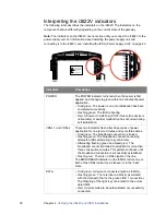
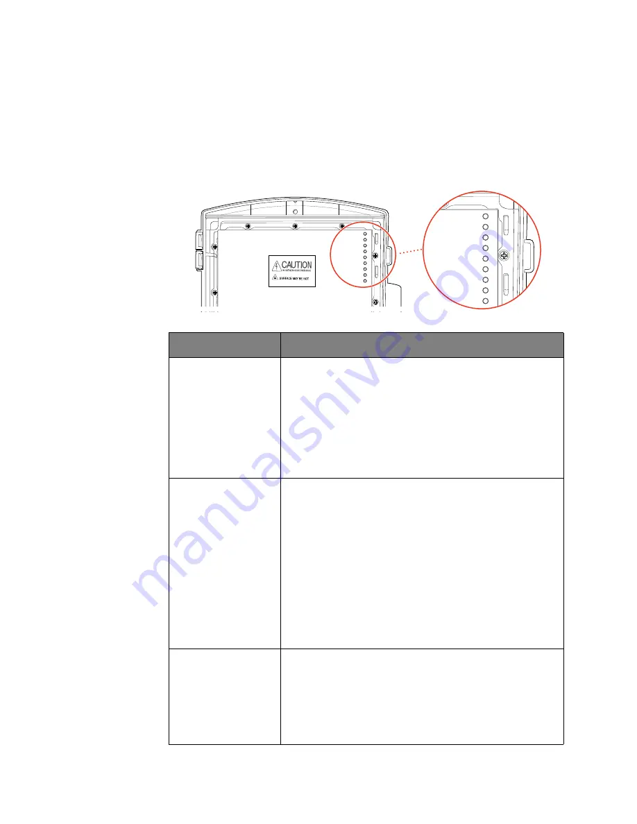
The following table describes the indicators on the i3822V. The indicators on the
component behave differently depending on the current state of the gateway.
Note:
The indicators on the i3822V are not active until you connect the i3822V to the
power supply unit. For information about installing the power supply unit and
connecting it to the i3822V, see “Installing the iPSU (Power Supply Unit)” on page 23.
Indicators
Description
POWER
The POWER indicator turns red when the power is first
applied, and changes to green within two minutes of power
application.
•
Solid green
. The power is on and initialization has been
completed successfully.
•
Flashing green
. The iNID is booting.
•
Red
. A Power-On Self-Test (POST) failure (the device is
unbootable) or another malfunction has occurred during
self initialization.
VDSL 1 and VDSL 2
These two indicators flash after 60 seconds of power
application for one to two minutes and cycle three times.
•
Solid green
. The broadband connection is trained.
•
Flashing green
. The broadband connection is being
attempted (DSL attempting to synchronize).
•
Alternating flashing green and steady red
. The
broadband connection failed to establish for more than
three consecutive minutes. This pattern continues until
the broadband connection is successfully established.
•
Flashing red
. There is no DSL signal on the line.
The BROADBAND indicator on the i38HG mirrors one or
both of the VDSL indicators, whichever is in the “best”
state.
DATA
•
Solid green
. A device is connected (such as i38HG).
•
Flashing green
. There is inbound activity associated
with the data port (that is, the green LINE 1 connection).
The flickering of the light is synchronized to the actual
data traffic.
•
Red
. A device failed to be authenticated or successfully
connected.
POWER
VDSL 1
VDSL 2
DATA
COAX
LINE 1
LINE 2
ETHERNET
BATTERY
POWER
VDSL 1
VDSL 2
DATA
COAX
LINE 1
LINE 2
ETHERNET
BATTERY

