18
Chapter 2
Installing the i3822V (Outside Unit)
CAUTION:
When connected, the i3822V receives power from the iPSU. Make sure
that the AC power adapter and the battery on the iPSU are not connected, or an
electrical shock may result.
To connect power supply lines:
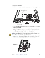
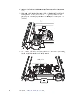
1. Cut an opening on the right grommet entry for the power supply line to fit through.
Note:
Use an appropriate tool to cut or punch through the grommet. Make the cut
just big enough for the line to fit through. The grommet prevents insects from
entering the inside of the unit. Make sure to seal any extra gaps on the cuts.
2. Insert the power supply line through the opening of the grommet entry.
Note:
Do not remove the protective gel-filled insulation around the holes; it acts as
a moisture barrier and prevents unwanted small particles from having direct
contact with the wires.
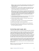
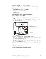
3. Lift up the POWER connector plastic rocker tab to expose the color-coded holes
on the right side of the unit.
4. Insert the un-stripped color-coded power supply wire pair as far as it can go into
each hole that matches the wire color: red is positive and black is negative.
You may feel an initial resistance when inserting the wires into the connector. Do
not stop there. If you do, the connectors might close on the insulation, but no
contacts are made.
Make sure that the wires have pierced the gel-filled insulation and that the inserted
wire ends are straight and have no curls on them. If the wires are bent upward or
curled when inserted, they will not make proper contact. This may result in the
wires passing the pull test even though there is no connection.
Note:
The power supply insulation-displacement connector (IDC) on the i3822V
and the iPSU are colored with the same polarity. Make sure to maintain polarity:
red is positive, black is negative. If wires are reversed, the i3822V will not power
up.
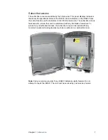
Power connector

