background image

5.Front Panel Operation


14 

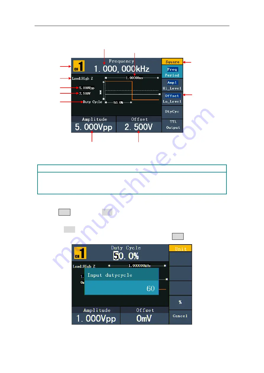
the output signal is set to 2.5Vpp amplitude and 1.25V offset. 

Channel

Setting menu of 
Square signal

Amplitude

Load

Offset

Current signal

Frequency

Parameter 1

Duty cycle

Parameter 2

Parameter 3


Figure 5-4: The User Interface of Square Signal 

Term Explanation 

Duty Cycle: 


The percentage that the High Level takes up the whole Period. 

To Set the Duty Cycle 

(1) 

Press 

  F4 

  button,  the "Duty"  menu item is highlighted,  the current value of the 

Duty cycle is displayed in 

Parameter 1

.   

(2) 

Turn the 

knob

 to change the value directly; 

or press the number keys to input the desired value, press 

  F4 

  to choose "%".   


Figure 5-5: Set the Duty cycle of Square signal 

Summary of Contents for AG1012F

Page 1: ...Dual Channel Arbitrary Waveform Generator User Manual AG1012F AG1022F AG2052F AG2062F WWW OWON COM CN ...

Page 2: ...at in the materials published originally The information in this manual was correct at the time of printing However LILLIPUT will continue to improve products and reserves the rights to change specification at any time without notice is the registered trademark of the LILLIPUT Company Fujian LILLIPUT Optoelectronics Technology Co Ltd No 19 Heming Road Lantian Industrial Zone Zhangzhou 363005 P R C...

Page 3: ...not apply to any defect failure or damage caused by improper use or improper or inadequate maintenance and care LILLIPUT shall not be obligated to furnish service under this warranty a to repair damage resulting from attempts by personnel other than LILLIPUT representatives to install repair or service the product b to repair damage resulting from improper use or connection to incompatible equipme...

Page 4: ...To Set the Frequency Period 12 To Set the Amplitude 13 To Set the Offset 13 To Set the High Level 13 To Set the Low Level 13 To Output Square Signals 13 To Set the Duty Cycle 14 To Output Ramp Signals 15 To Set the Symmetry 15 To Output Pulse Signals 16 To Set the Pulse Width Duty Cycle 17 To Output Noise Signals 17 To Output Arbitrary Signals 18 To Select the Built in Waveform 19 The User Definab...

Page 5: ...eter 34 To Set the Bright 34 To Set the Separator 34 To Set the Screen Saver 34 To Set the Counter 35 To Set Output Parameter 35 To Set the Output Load 35 To Set the Phase Deviation 36 To Set the System 36 Language Setting 36 Power On Setting 36 To Return to Default Setting 36 To Set the Beep 38 View System Information 38 To Set the Clock Source 38 To Use the Power Amplifier Optional 38 To Use Bui...

Page 6: ... grounded The product must be grounded properly before any connection with its input or output terminal Check all Terminal Ratings To avoid fire or shock hazard check all ratings and markers of this product Refer to the user s manual for more information about ratings before connecting to the instrument Do not operate without covers Do not operate the instrument with covers or panels removed Use P...

Page 7: ... in damage to this product or other property Terms on the Product The following terms may appear on this product Danger It indicates an injury or hazard may immediately happen Warning It indicates an injury or hazard may be accessible potentially Caution It indicates a potential damage to the instrument or other property might occur Safety Symbols Symbols on the Product The following symbol may ap...

Page 8: ...ore alternative solutions for users Features and benefits 3 9 inch high resolution 480 320 pixels TFT LCD display Advanced DDS technology max 60 MHz frequency output Max Sample rate 300 MSa s Frequency resolution 1 μHz Vertical resolution 14 bits max 1 M waveform record length Abundant waveform output 5 basic waveforms and 45 built in arbitrary waveforms output Exponential rise Exponential fall Si...

Page 9: ...4 Quick Start This chapter will deal with the following topics mainly Front Rear Panel Overview User Interface Overview How to Implement General Inspection How to Adjust the Foot Stools How to Implement Power On Check ...

Page 10: ...ch the character of the soft keyboard when entering file name In Sweep and N Cycle Burst if you choose Source as Manual every time you press this knob the generator will be triggered once In signal output interface press this knob to enter Channel Copy menu Direction key Move the cursor of the focused parameter or select the file locations Save button Store recall the user defined arbitrary wavefo...

Page 11: ...tion Mod Generate the Modulated waveforms Sweep and Burst these functions are only used for CH1 Both button Display the editable parameters of both channels When the function is enabled the backlight of the button turns on USB port Connect with an external USB device such as connect a USB device to the instrument Waveform selection buttons Include Sine Square Ramp Pulse Noise and Arbitrary wavefor...

Page 12: ...xternal signal source in Sweep Burst and FSK mode Ref Clk Counter In connector To accept an external clock signal or to accept the input signal of counter See page 38 To Set the Counter Ref Clk Out connector To synchronize generators Output a clock signal generated by the crystal inside the generator See page 38 To Set the Clock Source P Output connector Signal output for the Power Amplifier See p...

Page 13: ...d its accessories succeed in the electrical and mechanical property tests 2 Check the Accessories The supplied accessories have been already described in the Appendix A Enclosure of this Manual You can check whether there is any loss of accessories with reference to this description If it is found that there is any accessory lost or damaged please get in touch with the distributor of LILLIPUT resp...

Page 14: ...nel To change the voltage scale of the instrument do the following steps 1 Turn off the power button at the front panel and remove the power cord 2 Regulate the Power Switch to the desired voltage scale Power On 1 Connect the instrument to the AC supply using the supplied power cord Warning To avoid electric shock the instrument must be grounded properly 2 Press down the power button at the front ...

Page 15: ...ut Sine Signals How to Output Square Signals How to Output Ramp Signals How to Output Pulse Signals How to Output Noise Signals How to Output Arbitrary Signals How to Output DC How to Generate the Modulated Waveform How to Generate Sweep How to Generate Burst How to Save and Recall How to Set the Utility Function How to Use Built in Help ...

Page 16: ...current parameter such as Frequency Period To edit parameter Turn the knob to change the value of cursor position Press direction key to move the cursor The number keys can not be used to input CH1 Waveform Parameter 1 Parameter 4 CH2 Waveform Parameter 1 Parameter 2 Parameter 3 Parameter 2 Parameter 3 Figure 5 1 The User Interface of Both button To Turn On Off Output of Channels Press CH1 or CH2 ...

Page 17: ...ine signal Amplitude Load Offset Current signal Frequency Parameter 3 Parameter 2 Parameter 1 Sine Figure 5 2 The User Interface of Sine Signal To Set the Frequency Period Press F1 button the chosen menu item is highlighted the focused parameter is displayed in Parameter 1 Press F1 button to switch between Frequency Period Two methods to change the chosen parameter Turn the knob to change the valu...

Page 18: ...he knob or the number keys to set the desired value To Set the Low Level Press F3 confirm whether the Lo_Level menu item is highlighted if not press F3 to switch into Lo_Level In Parameter 3 a cursor appears under the value of offset Use the knob or the number keys to set the desired value To Output Square Signals Press button to call the user interface of Square signal the Square waveform paramet...

Page 19: ...5 4 The User Interface of Square Signal Term Explanation Duty Cycle The percentage that the High Level takes up the whole Period To Set the Duty Cycle 1 Press F4 button the Duty menu item is highlighted the current value of the Duty cycle is displayed in Parameter 1 2 Turn the knob to change the value directly or press the number keys to input the desired value press F4 to choose Figure 5 5 Set th...

Page 20: ...itude High Level Offset Low Level please refer to To Output Sine Signals on page 12 Channel Setting menu of Ramp signal Amplitude Load Offset Current signal Frequency Parameter 1 Symmetry Parameter 2 Parameter 3 Figure 5 6 The User Interface of Ramp Signal Term Explanation Symmetry The percentage that the Rising Period takes up the whole Period To Set the Symmetry 1 Press F4 button the Symmetry me...

Page 21: ... Pulse waveform are Frequency Period Amplitude High Level Offset Low Level Pulse Width Duty You can operate the menu by using the menu selection buttons on the right To set the Frequency Period Amplitude High Level Offset Low Level please refer to To Output Sine Signals on page 12 Channel Setting menu of Pulse signal Amplitude Load Offset Current signal Frequency Pulse width Parameter 2 Parameter ...

Page 22: ...tem is highlighted the focused parameter is displayed in Parameter 1 Press F4 to switch between Pulse Width Duty 2 Turn the knob to change the value directly or press the number keys to input the desired value and choose the unit Figure 5 9 Set the Pulse Width of Pulse signal To Output Noise Signals The noise signal which the generator output is white noise Press button to call the user interface ...

Page 23: ...veform are Frequency Period Amplitude High Level Offset Low Level Built in Waveform Editable Waveform You can operate the menu by using the menu selection buttons on the right To set the Frequency Period Amplitude High Level Offset Low Level please refer to To Output Sine Signals on page 12 The Arbitrary signal consists of two types the system built in waveform and the user definable waveform Chan...

Page 24: ... Press F1 to output the Exponential Rise waveform Built in Waveform Table Name Explanation Common StairD Stair down waveform StairU Stair up waveform StairUD Stair up and stair down waveform Trapezia Trapezoid waveform RoundHalf RoundHalf wave AbsSine Absolute value of a Sine AbsSineHalf Absolute value of half a Sine SineTra Sine transverse cut SineVer Sine vertical cut NegRamp Negative ramp AttAL...

Page 25: ...uss Gauss distribution Hamming Hamming window Hann Hanning window Bartlett Bartlett window Blackman Blackman window Laylight Laylight window Triang Triangle window Fejer window Others DC DC signal Heart Heart signal Round Round signal LFMPulse Linear FM pulse Rhombus Rhombus signal Cardiac Cardiac signal The User Definable Waveform Press button and press F5 to select Editable Wform Menu item Instr...

Page 26: ...your needs Press F4 to choose Store enter the file system If a USB device is connected press direction key to select the storage USBDEVICE is the USB device storage FLASH is the internal storage Choose Next level enter the desired storage path choose Save an input keyboard pops up input the file name and then choose DONE How to Select a Stored Waveform 1 Enter the operation menu Press Editable Wfo...

Page 27: ...ut from SDS series oscilloscope manufactured by OWON and saved to USB device or cut by the software of OWON oscilloscope Then ARB waveform generators can output the same signal as the cut wave Use SDS Series oscilloscope manufactured by OWON to cut wave 1 Connect USB device to SDS series oscilloscope 2 Press Save to call out the save menu 3 Press the H1 button the Type menu will display at the lef...

Page 28: ...ators to recall wave 1 Enter the operation menu Press Editable Wform SelectWform Enter the following interface Figure 5 14 Choose storage device 2 Select USBDEVICE enter The Next Level Turn the knob or press direction key to select the saved example ota waveform file ...

Page 29: ... wave cut from oscilloscope contains data number more than 8192 AG1012F and AG1022F will compress data On the contrary if the data number is less than 8192 AG1012F and AG1022F will use linear interpolation 3 The max data number of AG2052F AG2062F ARB is 1000000 When the wave cut from oscilloscope contains data number more than 1000000 generators will compress data On the contrary if the data numbe...

Page 30: ...d function button then press F1 to select Mod 2 Press F1 to switch Mod Type to AM If the Carrier Waveform is not Sine the system will switch it to Sine automatically 3 Press button to display the waveform and parameters of the Carrier Waveform You can change the parameters please refer to To Output Sine Signals on page 12 Press button again to return to the Modulation mode interface 4 Press F5 to ...

Page 31: ...ltage of the modulating waveform The user interface of the FM is shown as below Current Parameter Carrier Frequency Carrier Amplitude Carrier Waveform Modulating Waveform Load Frequency Deviation FM Frequency Mod Type Mod Shape Source Figure 5 18 The User Interface of FM How to set the parameters of FM 1 Press Mod function button then press F1 to select Mod 2 Press F1 to switch Mod Type to FM If t...

Page 32: ...M Phase Modulation The modulated waveform consists of two parts the Carrier Waveform and the Modulating Waveform The Carrier Waveform can only be Sine In PM the phase of the Carrier Waveform varies with the instantaneous voltage level of the modulating waveform The user interface of the PM is shown as below Current Parameter Carrier Frequency Carrier Amplitude Carrier Waveform Modulating Waveform ...

Page 33: ...e Hop Frequency The Frequency of the Output Frequency switch between the carrier waveform frequency and the Hop frequency is called the FSK rate The frequency by which the output frequency switch from each other is determined by the Internal Frequency generator or the Signal Voltage Level offered by the Ext Trig Burst Fsk In connector in the rear panel The Carrier Waveform can only be Sine The use...

Page 34: ...ameters of PWM 1 Press Mod function button then press F1 to select Mod 2 Press F1 to switch Mod Type to PWM If the Carrier Waveform is not Pulse the system will switch it to Pulse automatically 3 Press button to display the waveform and parameters of the Carrier Waveform You can change the parameters please refer to To Output Pulse Signals on page 16 Press button again to return to the Modulation ...

Page 35: ...o set signals on page 12 Press button again to return to the Sweep mode interface 3 Press F1 to set Sweep Time the Time Span of the Sweep for which the Frequency changes from the Start Frequency to Stop Frequency 4 Press F2 to select the Sweep Type Linear means setting the Sweep with linear spacing Log means setting the Sweep with logarithmic spacing 5 Use Start Freq and Stop Freq or Center Freq a...

Page 36: ...on within every Signal Generator N Cycle Burst N Cycle has specific number of waveform cycles and every burst is activated by a trigger event Gated Burst Gated burst use external source to control burst as when to be activated Set the N Cycle Burst Current Parameter Cycles Load Start Phase N Cycle Waveform Source Figure 5 22 The User Interface of N Cycle Burst 1 When the output signal is Sine Squa...

Page 37: ...he internal source External means using the Ext Trig Burst Fsk In connector in the rear panel to input the external signal Manual means choosing manual trigger in N Cycle Burst interface press the knob on the front panel to output a burst signal Set the Gated Burst Current Parameter Positive Load Start Phase Gated Waveform Source Figure 5 23 The User Interface of Gated Burst 1 When the output sign...

Page 38: ...to choose the desired storage Press F1 to enter the chosen storage Provide operations as Next level Up one level New folder Delete Rename Copy Paste 3 Remove the USB device Remove the USB device from the USB port on the front panel The system will inform you The USB device is removed and the USBDEVICE in the storage menu will disappear To Edit the File Name In file system the user can edit the nam...

Page 39: ...ct the unit The bright range is 0 100 To Set the Separator The user can set the separator of the displayed parameter 1 Press Utility and choose Disp Setup press F2 to select Sep 2 Press F2 to switch between Comma Space Off Take the Frequency parameter for instance Comma Space Off To Set the Screen Saver The screen saver will run automatically if no operation is taken for any key within the set tim...

Page 40: ...nob to change the value press direction key to move the cursor left and right or press the number keys to input the desired value and choose the unit The range of trig levle is 2 5 V 2 5 V Press F5 to choose Back to previous menu view the result After all the set was done the counter will measure the signal according to the current set If the reading is unsteady please repeat the above step until ...

Page 41: ... input the desired value in degree press F4 to select the unit The phase deviation range is 0 360 To Set the System Language Setting Press Utility and choose System press F1 to switch display languages Power On Setting 1 Press Utility and choose System press F2 to select Power On 2 Press F2 to switch between Default Last Default means that all the settings return to default when powered Last means...

Page 42: ...00 Hz PM Phase Deviation 0 FSK Hop Frequency 100 Hz FSK Frequency 100 Hz Source Internal Sweep Default Start Stop Frequency 100 Hz 1 kHz Time 1 sec Mode Linear Burst Default Frequency 1 kHz Count 1 Cycle Period 1 sec Phase 0 Others Default Brightness 95 Separator Comma Screen Saver time 100 minutes Load High Z Phase Deviation 0 Clock Source Internal Channel Output Control Off ...

Page 43: ...Note The amplitude of the Ref Clk Counter In input signal must be over 1 V 1 Press Utility and choose System enter the second page of the menu 2 Press F3 to select CLK Sou 3 Press F3 to switch between Internal External To Use the Power Amplifier Optional The Power Amplifier module is optional for the generator can be used in power circuit test power components measurement constant voltage output m...

Page 44: ...tion button the catalog will display in the screen 2 Press F1 or F2 to choose help topic or just turn the knob to choose 3 Press F3 to view the details about the topic press F5 to go back to the catalog 4 Press Help again to exit the help or just do other operations ...

Page 45: ...stall the driver When the Waveform Generator is turned on a dialog will appear on the PC screen and guide you to install the USB driver The driver is in the USBDRV folder under the directory where the ultrawave communication software is installed such as C Program Files OWON ultrawave USBDRV 3 Port setting of the software Run the ultrawave software click Communications in the menu bar choose Ports...

Page 46: ... AC Power socket is used appropriately and in good condition the cover can be pried open with a straight screwdriver Restart the instrument after the steps above If the problem still exists please contact LILLIPUT for our service 2 The measured value of output signal amplitude disaccords to the displayed value Check if the actual load matches the set one Please refer to To Set the Output Load on p...

Page 47: ...istic Frequency resolution 1 μHz AG1012F AG1022F Max sampling rate 125 MSa s AG2052F AG2062F Max sampling rate 300 MSa s Sine AG1012F 1 μHz 10 MHz AG1022F 1 μHz 25 MHz AG2052F 1 μHz 50 MHz AG2062F 1 μHz 60 MHz Square AG1012F AG1022F 1 μHz 5 MHz AG2052F 1 μHz 25 MHz AG2062F 1 μHz 30 MHz Ramp 1 μHz 1MHz Pulse AG1012F AG1022F 1 μHz 5 MHz AG2052F 1 μHz 10 MHz AG2062F 1 μHz 15 MHz White Noise 25 MHz ba...

Page 48: ...2 dB 10 MHz to 25 MHz 0 3 dB 25 MHz to 50 MHz 0 5 dB Harmonic Distortion when the Amplitude is 1 0 Vp p AG1012F AG1022F AG2052F AG2062F 40 dBc Total Harmonic Distortion when the Amplitude is 1 Vp p 10 Hz to 20 kHz 0 2 Phase Noise 110 dBc Hz at 1 MHz frequency 10 kHz offset 1 Vp p typical Residue Clock Noise 57 dBm typical Square Rise Fall Time 12 ns 10 90 typical 1 kHz 1 Vp p Jitter rms AG1012F AG...

Page 49: ...Minimum Rise Fall Time 35 ns typical Jitter RMS 6 ns 30 ppm Modulated Waveform AM Carrier Waveforms Sine Source Internal External Internal Modulating Waveforms Sine Square Ramp White Noise Arbitrary Internal AM Frequency 2 mHz 20 kHz Depth 0 0 100 0 FM Carrier Waveforms Sine Source Internal External Internal Modulating Waveforms Sine Square Ramp White Noise Arbitrary Internal Modulating Frequency ...

Page 50: ... 1 to 50 000 periods infinite gated Start Phase 360 360 Internal Period 10 ms 500 s 1 Gated Source External Trigger Trigger Sources Source External or Manual Counter Specification Function Frequency period positive Pulse width Duty cycle Frequency Range Single channel 100 mHz 200 MHz Frequency Resolution 6 digits Voltage Range and Sensitivity non modulation signal DC coupled DC offset range 1 5 VD...

Page 51: ...d Input voltage swing 100 mVp p to 5 Vp p Locking range 10 MHz 9 kHz Counter Input share the same port as External Reference Clock Input DC coupled DC offset range 1 5 VDC 100 mHz 100 MHz 250 mVp p 5 Vp p AC DC 100 MHz 200 MHz 450 mVp p 3 Vp p AC DC AC coupled 1 Hz 100 MHz 250 mVp p 5 Vp p 100 MHz 200 MHz 450 mVp p 4 Vp p External Reference Clock Output Impedance 50 kΩ AC coupled Amplitude 3 3 Vp ...

Page 52: ... 240 VAC 100 120 VAC 50 60 Hz CATⅡ Consumption Less than 18 W Fuse 250 V F2AL Environment Temperature Working temperature 0 40 Storage temperature 20 60 Relative Humidity 90 Height Operating 3 000 m Non operating 15 000 m Cooling Method Fan cooling Mechanical Specifications Dimension 235 mm 110 mm 295 mm W H D Weight 3 kg Interval Period of Adjustment One year is recommended for the calibration in...

Page 53: ... operating conditions require To clean the instrument exterior perform the following steps 1 Wipe the dust from the instrument surface with a soft cloth Do not make any scuffing on the transparent LCD protection screen when clean the LCD screen 2 Disconnect power before cleaning your instrument Clean the instrument with a wet soft cloth not dripping water It is recommended to scrub with soft deter...

Reviews: