90-0761 V4
© 2018 Owlstone Medical Ltd
Proprietary and Confidential
Page 1 of 22
Owlstone ultraFAIMS-T1 Hardware Installation User Manual
Page 1: ...90 0761 V4 2018 Owlstone Medical Ltd Proprietary and Confidential Page 1 of 22 Owlstone ultraFAIMS T1 Hardware Installation User Manual ...
Page 2: ...Instruments 3 Safety notice 3 Contacting Owlstone Medical Ltd 4 System Description 5 SYSTEM FAMILIARISATION 5 SAFETY INFORMATION 8 INSTALLING THE T1 SYSTEM 9 GETTING STARTED USING ULTRAFAIMS 17 REMOVING THE ULTRAFAIMS UNIT 17 CHANGING A CHIP SEALER ASSEMBLY 18 TROUBLESHOOTING 22 Status LED Indications 22 Technical Support 22 APPENDIX OPERATING CONDITIONS 22 ...
Page 3: ...pplied system is in compliance with international regulations If this system is used in a manner not specified by Owlstone Medical Ltd the protection provided by the system could be impaired Safety notice Always observe the following safety precautions Use only the mains adaptor and leads supplied This equipment is for use in moderate climates only see Appendix Do not use the equipment in damp or ...
Page 4: ...cal Ltd Visit the OWLSTONE support website http support owlstonenanotech com for up to date contact details and service support UK Office 183 Cambridge Science Park Milton Road Cambridge CB4 0GJ Tel 44 0 1223 428 200 US Office Owlstone Inc Suite 202 19 Ludlow Road Westport CT 06880 USA Tel 1 203 908 4848 ...
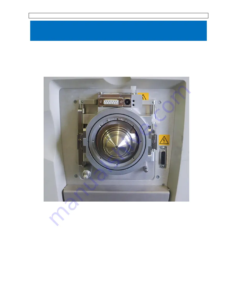
Page 5: ...or Orbitrap Mass Spectrometers These notes are provided to assist with understanding how to set up and use the system safely See the Owlstone ultraFAIMS user interface software manual OW 003401 TM for further information on FAIMS separation System Familiarisation The system consists of the following items 1 UltraFAIMS Control Unit 01 0480 The control unit generates the FAIMS waveforms needed to dr...
Page 6: ...ace 4 Chip Cone Cap 01 0401 The chip cone cap holds the chip sealer assembly in place on the back cone interface A chip sealer assembly is shown fitted in the center 5 Adaptor Plate 01 0400 The adaptor plate ring is the interface between the mass spectrometer the FAIMS module and the ionisation source 6 Connection Extender 01 0355 The connection extender is the interface between the mass spectrome...
Page 7: ...ssembly is attached 8 Support extender pin 01 0479 The support extender pin fits over one of the ionisation source support pins to allow the source to be supported when the adaptor plate is in place 9 Power supply 01 0320 The power supply consists of a 24V power supply brick with a custom connector 10 External trigger cable 13 0165 Information on how to use the external trigger cable is available ...
Page 8: ...ck on the RF waveform feeder ensures that these voltages are disabled when the RF waveform feeder is not connected to the adaptor ring Do not override this interlock This would result in hazardous voltages being accessible on the pins of the DF feeder The ultraFAIMS system is not designed to operate without a chip sealer assembly installed Do not try to run the system without o the chip sealer ass...
Page 9: ...ck the MS user manual to discover how to do this 2 As supplied the chip cone cap is screwed onto the T1 back cone Unscrew this Do NOT fit the PTFE gasket at first as it may not be needed The image shows how it should be fitted IF REQUIRED Do NOT tighten the screws holding the internal insert in place this must be slightly loose when fitted to the mass spectrometer Leave both screws loose by 2 3 tu...
Page 10: ...re a good seal around the rear face of the T1 back cone push the cone towards the MS inlet while tightening the grub screws Tighten finger tight all 3 grub screws and work around the T1 back cone to retighten and check them 5 Choose the chip type to be used NC or ND and insert the chip sealer assembly into the chip cone cap aligning the notch feature as shown Check the chip for any visible particl...
Page 11: ...e 7 Push the chip cone innerinto position over the o ring It should stay in position on the T1 back cone 8 Screw in the chip cone cap outer part and tighten Tightening this sufficiently is essential as this pushes the small o ring inside the T1 back cone onto the capillary on the mass spectrometer to form a seal Locating pin for cap Alignment feature for locating cap onto cone ...
Page 12: ...kets above the inlet and the mounting rods fitted to the side catches 10 Rotate the rods to hold the adaptor plate ring in place The rods can be stiff to turn and the left hand one may require some force to rotate Adjusting the latch blocks forward and using metal shims behind them may help Ensure the large o ring is in place in the groove on the outer face 11 Fit the connection extender above the...
Page 13: ...n the mass spectrometer 13 If not already done fit the waveform RF feeder to the control module using the M3x12 screws supplied Note the orientation of this part with the slope of the metal to the outside of the box to get the correct alignment of the pins on the bottom of the waveform RF feeder 14 Use the supplied 2 5mm hex key to tighten all 4 screws ...
Page 14: ...he replaceable pogo pins are fitted in the feeder 16 Insert the connector of the waveform feeder into the socket on the right side of the adaptor plate ring 17 Adjust the extendable feet on the bottom of the control module so that it sits on the bench If extra height is needed a stand can be provided Pogo pin ...
Page 15: ...waveform DF feeder and the adaptor plate ring 19 The ionisation source can now be mounted onto the adaptor plate ring in the same way it is normally attached to the mass spectrometer The latch blocks are set to be 1 7mm from the face but may need adjusting if the ionisation source doesn t fit A Vernier calliper could be used to check that it they are parallel to the front face Insert M3x10 screw L...
Page 16: ...tation of this plug as it can be forced on the wrong way around 22 Connect the interlock cable attached to the waveform DF feeder to the Interlock socket on the control module 23 If using the external trigger cable connect this to the socket labelled MS Interface 24 Install the PC interface software See OW 003401 TM Owlstone UltraFAIMS control software manual for details of how to do this This sof...
Page 17: ...lstonenanotech com hc en us sections 202712206 Removing the UltraFAIMS unit To remove the UltraFAIMS unit from the mass spectrometer please follow the above steps in reverse In particular note that the adaptor plate ring and T1 back cone cannot be removed until the waveform RF feeder connector has been pulled out of the adaptor plate ring Fuse Power connector Power switch External trigger comms co...
Page 18: ...one 2 The PTFE chip sealer assembly is held in place in the cap by a single catch To remove the chip sealer assembly depress the catch which can be accessed via the hole in the inner ring of the cap using tweezers or other suitable tool and lever the PTFE mount out IMPORTANT do not try to remove by pulling on the gold connector pins as this may damage the chip z UltraFAIMS chip sealer assembly mod...
Page 19: ...the chip sealer assembly is completely dry before applying FAIMS waveforms to the cleaned chip Further advice on cleaning can be found on the Owlstone support website https support owlstonenanotech com hc en us categories 201660986 4 To replace the chip sealer assembly in the cap align the alignment feature bump in the PTFE mount with the corresponding recess in the inner ring of the cap and push ...
Page 20: ...onfidential Page 20 of 22 5 Align the gold connector pins with the holes in the T1 back cone and the alignment feature on the inner ring of the cap with the locating pin in the T1 back cone Locating pin for cap Alignment feature for locating cap onto cone ...
Page 21: ...90 0761 V4 2018 Owlstone Medical Ltd Proprietary and Confidential Page 21 of 22 6 Screw the chip cone cap back tightly onto the T1 back cone Reminder Do not operate the system without a chip attached ...
Page 22: ...n a cooler location 3 RF fan failure Check that the fan can still be heard and that it is blowing air 4 RF PSU overvoltage This means the RF 135 power supply went above a safety level of 140V and caused the RF sub system to be reset This may mean that this power supply has failed Red This indicates an unrecoverable error however if the cause of the fault e g a short of the connection pins is remov...