OV915WVA User Manual
Copyright @ 2016 OvisLink (Canada) INC All rights reserved
21
5.2 Advanced Setup
Choose
Advanced Setup
and the submenus of
are shown as
below:
Page 1: ...OV915WVA User Manual VER 1 0 OvisLink Canada INC ...
Page 2: ... Installation 8 3 2 1 Choosing the Best Location for Wireless Operation 8 3 2 2 Connecting the Device 9 4 PC Network Configuration and Login 10 4 1 PC Network Configuration 10 4 2 Logging In to the DSL Router 11 5 Web Based Management 13 5 1 Device Information 13 5 1 1 Summary 13 5 1 2 WAN 14 5 1 3 Statistics 15 5 1 4 LAN 15 5 1 5 WAN Service 15 5 1 6 xTM 16 5 1 7 xDSL 16 5 1 8 Route 19 5 1 9 ARP ...
Page 3: ...nterface Grouping 77 5 2 17 IP Tunnel 79 5 2 18 IPSec 81 5 2 19 Certificate 83 5 2 20 Power Management 88 5 2 21 Multicast 88 5 3 Wireless 89 5 3 1 Basic Settings 90 5 3 2 Security 92 5 3 3 MAC Filter 101 5 3 4 Wireless Bridge 102 5 3 5 Advanced Settings 103 5 3 6 Station Info 106 5 4 Diagnostics 106 5 4 1 Diagnostics 106 5 5 Management 107 5 5 1 Settings 108 5 5 2 System Log 109 5 5 3 Security Lo...
Page 4: ...OV915WVA User Manual Copyright 2016 OvisLink Canada INC All rights reserved iii 5 5 8 Reboot 117 6 Q A 118 ...
Page 5: ...y If you find any damage replace it at once Proper space left for heat dissipation is necessary to avoid any damage caused by overheating to the device The holes on the device are designed for heat dissipation to ensure that the device works normally Do not cover these heat dissipation holes Do not put this device close to a place where a heat source exits or high temperature occurs Avoid the devi...
Page 6: ...ber The OV915WVA is easy to install and use The Router connects to an Ethernet LAN or computers via standard Ethernet ports The xDSL connection is made using ordinary telephone line with standard connectors The advanced security enhancements packet filtering and port redirection can help protect your network from potentially devastating intrusions by malicious agents from outside your network Netw...
Page 7: ...ort for up to 8 PPPoE sessions Support RIP v1 RIP v2 WLAN with high speed data transfer rates compatible with IEEE 802 11b g n IP routing and bridging Asynchronous transfer mode ATM and digital subscriber line DSL support Point to point protocol PPP Network port address translation NAT PAT Quality of service QoS Wireless LAN security WPA 802 1x RADIUS client Universal plug and play UPnP Print serv...
Page 8: ... reserved 4 ITU G 992 1 G dmt ITU G 992 2 G lite ITU G 994 1 G hs ITU G 992 3 ADSL2 ITU G 992 5 ADSL2 ITU G 993 2 VDSL ITU T G 9700 G 9701 G fast 3G WCDMA CDMA2000 TD SCDMA ANSI T1 413 Issue 2 IEEE 802 3 IEEE 802 3u IEEE 802 11b IEEE 802 11g IEEE 802 11n IEEE 802 11ac ...
Page 9: ...tion Power Green On The device is powered on and the device operates normally Blink The software is upgrading Off The device is powered off Red On The device is initiating Blink The software is upgrading DSL Green On DSL link has established Blink The DSL line is training Off Device is powered off Internet Green On Internet is synchronized successfully in the route mode Blink Internet data is bein...
Page 10: ...is disabled 5G Green On WLAN is enabled Blink Data is being transmitted through the wireless interface Off WLAN is disabled WPS Green On Connection succeeds under Wi Fi Protected Setup Blink Negotiation is in progress under Wi Fi Protected Setup Off Wi Fi Protected Setup is disabled USB1 Green On The connection of 3G or USB flash disk has established Blink Data is being transmitted Off No signal i...
Page 11: ... following table describes the interfaces or the buttons Interface Description DSL RJ 11 port Connect the router to DSL connector or splitter through telephone cable LAN 1 4 RJ 45 port for connecting the router to a PC or another network device Reset Press the button for at least 1 second and then release it System restores the factory default settings ...
Page 12: ...02 11n function press the button for more than 5 second and then release it enable WPS PBC mode if WPS is enabled the wireless router starts to accept the negotiation of PBC mode Fiber Fiber port for connecting the device to a G Fast optical module Warning Do not press the Reset button unless you want to clear the current settings The Reset button is in a small circular hole on the rear panel If y...
Page 13: ... depending on types of materials and background RF noise in your home or business 3 2 2 Connecting the Device Step 1 Connect the DSL port of the router The spliiter has 3 ports Line Connect to a wall phone jack RJ 11 jack Modem Connect to the Line interface of the router Fiber Connect to the optical module Step 2 Connect the LAN port of the router to the network card of the PC through an Ethernet ...
Page 14: ...ddress or be instructed to automatically obtain an IP address using the network DHCP server DSL router provides a DHCP server on its LAN and it is recommended to configure your LAN to automatically obtain its IP address and DNS server IP address The configuration principle is identical but should be carried out differently on each operating system The following displays the TCP IP Properties dialo...
Page 15: ... Click OK to save the settings 4 2 Logging In to the DSL Router To log in to the DSL router do as follows Open a Web browser on your computer Enter http 192 168 1 1 the default IP address of the DSL router in the address bar The login page appears Enter the user name and the password The default username and password of the super user are admin and admin The username and password of the common use...
Page 16: ...r Manual Copyright 2016 OvisLink Canada INC All rights reserved 12 Figure 6 Login page After logging in to the DSL router as a super user you can query configure and modify all the settings and diagnose the system ...
Page 17: ...ow to use Web based management of the DSL router which allows you to configure and control all of DSL router features and system parameters in a user friendly GUI 5 1 Device Information Choose Device Info and the submenus of Device Info are shown as below 5 1 1 Summary Choose Device Info Summary and the following page appears ...
Page 18: ... All rights reserved 14 This page displays the device information such as the board ID software version and the information of your WAN connection such as the upstream rate and the LAN address 5 1 2 WAN Choose Device Info WAN and the following page appears ...
Page 19: ...3 Statistics 5 1 4 LAN Choose Device Info Statistics LAN and the following page appears In this page you can view the statistical information about the recevied and transmitted data packets of the Ethernet and wireless interfaces Click Reset Statistics to restore the values to zero and recount them 5 1 5 WAN Service Choose Device Info Statistics WAN Service and the following page appears ...
Page 20: ...Reset Statistics to restore the values to zero and recount them 5 1 6 xTM Choose Device Info Statistics xTM and the following page appears In this page you can view the statistical information about the recevied and transmitted data packets at the xTM interfaces Click the Reset button to restore the values to zero and recount them 5 1 7 xDSL Choose Device Info Statistics xDSL and the following pag...
Page 21: ...OV915WVA User Manual Copyright 2016 OvisLink Canada INC All rights reserved 17 ...
Page 22: ...SL interfaces Click xDSL BER Test to test the xDSL Bit Error Rate Click Reset Statistics to restore the values to zero and recount them xDSL BER Test Click xDSL BER Test to perform a bit error rate BER test on the DSL line The test page is as follows The Tested Time sec can be 1 5 10 20 60 120 180 240 300 or 360 Select a time in the drop down list and click Start The following pages appear ...
Page 23: ...016 OvisLink Canada INC All rights reserved 19 When the ADSL BER test completes the following page appears Note If the BER reaches e 5 you cannot access the Internet 5 1 8 Route Choose Device Info Route and the following page appears ...
Page 24: ...and the following page appears In this page you can view the MAC address and IP address information of the device connected to the router 5 1 10 DHCP Choose Device Info DHCP and the following page appears In this page you can view the host name the IP address assigned by the DHCP server the MAC address this is corresponding to the IP address and the DHCP lease time ...
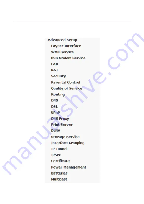
Page 25: ...OV915WVA User Manual Copyright 2016 OvisLink Canada INC All rights reserved 21 5 2 Advanced Setup Choose Advanced Setup and the submenus of Advanced Setup are shown as below ...
Page 26: ...oose Advanced Setup Layer2 Interface ATM Interface In this page you can add or remove to configure DSL ATM Interfaces Click Add to add ATM Interface and the following page appears In this page you can enter this PVC VPI and VCI value and select DSL link type EoA is for PPPoE IPoE and Bridge encapsulation mode service category ...
Page 27: ...IPoA Encapsulation Mode LLC SNAP BRIDGING or VC MUX Service Category UBR Without PCR UBR With PCR CBR Non Realtime VBR Realtime VBR Select Scheduler for Queues of Equal Precedence as the Default Queue Weighted Round Robin or Weighted Fair Queuing Click Apply Save to save the configuration and return the following page If you want to remove this Interface please select the Remove check box and clic...
Page 28: ...C All rights reserved 24 In this page you can configuration the PTM interface Click Apply Save Click Apply Save to save the configuration and return the following page If you want to remove this Interface please select the Remove check box and click Remove ...
Page 29: ...owing page appears In this page you can add or remove to configure ETH WAN Interfaces Click Add and the following page appears In this page you can select a ETH port Click Apply Save to save configuration Note If ETH Interface is selected there are two WAN service types PPPoE and IPoE 5 2 2 WAN Service Choose Advanced Setup WAN Service and the following page appears ...
Page 30: ...This section describes the steps for adding the PPPoE WAN service Step1 In the Wide Area Network WAN Service Setup page click the Add button to display the following page At first you must add a proper ATM interface for this WAN service Step2 In this page you can select a ATM Interface for the WAN service After selecting the ATM interface click Next to display the following page ...
Page 31: ...OV915WVA User Manual Copyright 2016 OvisLink Canada INC All rights reserved 27 Step3 In this page select the WAN service type to be PPP over Ethernet PPPoE Click Next to display the following page ...
Page 32: ... provided by your ISP PPPoE Service Name If your ISP provides it to you please enter it If not do not enter any information Authentication Method The value can be AUTO PAP CHAP or MSCHAP Usually you can select AUTO Enable Fullcone NAT NAT is one where all requests from the same internal IP address and port are mapped to the same external IP address and port Furthermore any external host can send a...
Page 33: ... connnection does not stop unless the modem is powered off and DSLAM or uplink equipment is abnormal PPP IP extension If you want to configure DMZ Host you should enable it first Use Static IPv4 Address If this function is disabled the modem obtains an IP address assigned by an uplink equipment such as BAS through PPPoE dial up If this function is enabled the modem uses this IP address as the WAN ...
Page 34: ...rved 30 Step6 In this page select a preferred WAN interface as the system default gateway and then click Next to display the following page Step7 In this page you can obtain the DNS server addresses from the selected WAN interface Click Next and the following page appears ...
Page 35: ...ave and apply the settings 5 2 2 2 Adding a MER IPoE WAN service This section describes the steps for adding the MER WAN service Step1 In the Wide Area Network WAN Service Setup page click the Add button to display the following page At first you must add a ATM interface for this WAN service Step2 Select an ATM Interface and then click Next to display the following page ...
Page 36: ...t 2016 OvisLink Canada INC All rights reserved 32 Step3 In this page select the WAN service type to be IP over Ethernet enter the service description for this service After finishing setting click Next to display the following page ...
Page 37: ...lect obtain an IP address automatically or manually enter the IP address provided by your ISP Click Next and the following page appears Note If selecting Obtain an IP address automatically DHCP will be enabled for PVC in MER mode If selecting Use the following Static IP address please enter the WAN IP address subnet mask and gateway IP address ...
Page 38: ... the network address translation settings for example enabling NAT enabling firewall and enabling IGMP multicast After finishing setting click Next and the following page appears Step6 In this page select a preferred WAN interface as the system default gateway and then click Next to display the following page ...
Page 39: ...nual Copyright 2016 OvisLink Canada INC All rights reserved 35 Step7 In this page you can obtain the DNS server addresses from the selected WAN interface After finishing setting click Next to display the following page ...
Page 40: ...g the PPPoA WAN service Step1 Choose Advanced Setup Layer2 Interface ATM Interface to dsipaly the DSL ATM Interface Configuration page In this page you need to add a PVC for PPPoA mode Click the Add button in the DSL ATM Interface Configuration page to display the following page Step2 Select the DSL link type to be PPPoA and select the encapsulation mode to be VC MUX according to the uplink equipm...
Page 41: ...d 37 Step3 Choose WAN Service and click Add to display the following page Step4 Select the proper interface for the WAN service and then click Next to display the following page Step5 In this page you may modify the service description Click Next to display the following page ...
Page 42: ...ress Dial on demand with idle timeout timer If this function is enabled you need to enter the idle timeout time Within the preset minutes if the modem does not detect the flow of the user continuously the modem automatically stops the PPPoA connection Once it detects the flow like access to a webpage the modem restarts the PPPoA dialup If this function is disabled the modem performs PPPoA dial up ...
Page 43: ...Enable IGMP Multicast Proxy If you want PPPoE mode to support IPTV enable it Step6 In this page you can enter the PPP username and PPP password provided by your ISP Select the authentication method according to your requirement After finishing setting click Next to display the following page Step7 In this page select a preferred WAN interface as the system default gateway and then click Next to di...
Page 44: ...nual Copyright 2016 OvisLink Canada INC All rights reserved 40 Step8 In this page you can obtain the DNS server addresses from the selected WAN interface After finishing setting click Next to display the following page ...
Page 45: ...he settings by clicking the Back button if necessary 5 2 2 4 Adding an IPoA WAN service This section describes the steps for adding the IPoA WAN service Step1 Choose Advanced Setup Layer2 Interface ATM Interface to dsipaly the DSL ATM Interface Configuration page In this page you need to add a PVC for IPoA mode Click the Add button in the DSL ATM Interface Configuration page to display the followi...
Page 46: ...ect the encapsulation mode to be LLC SNAP ROUTING according to the uplink equipment After finishing setting click the Apply Save button to save the settings Step3 Choose WAN Service and click Add to display the following page Step4 Select the proper interface for the WAN service and then click Next to display the following page ...
Page 47: ...xt to display the following page Step6 In this page enter the WAN IP address the WAN subnet mask and primary DNS server provided by your ISP and then click Next to display the following page In this page Network Address Translation NAT allows you to share one Wide Area Network WAN IP address for multiple computers on your Local Area Network LAN ...
Page 48: ...e Internet normally you need to add a route on the uplink equipment Otherwise the access to the Internet fails Normally please enable the NAT function Step7 After finishing setting click Next to display the following page Step8 In this page select a preferred WAN interface as the system default gateway and then click Next to display the following page ...
Page 49: ...formation about the IPoA settngs Click Apply Save to save and apply the settings You can modify the settings by clicking the Back button if necessary 5 2 2 5 Adding a Bridge WAN service This section describes the steps for adding the Bridge WAN service Step1 In the Wide Area Network WAN Service Setup page click the Add button to display the following page At first you must add a proper ATM interfa...
Page 50: ...OV915WVA User Manual Copyright 2016 OvisLink Canada INC All rights reserved 46 Step2 Select the proper ATM Interface and then click Next to display the following page ...
Page 51: ...yright 2016 OvisLink Canada INC All rights reserved 47 Step3 In this page you can select the WAN service type and modify the service description for this service After finishing setting click Next to display the following page ...
Page 52: ... Advanced Setup 3G WAN Service and the following page appears This page is used to configure 3G connection If you want to access the Internet through 3G connection a 3G network card is required Connect the 3G network card to the USB interface of the Router Information Click it to display the information of the 3G network card Pin Manage Click it to configure the 3G PIN Upload Driver For a un suppo...
Page 53: ...re allowed to configure the settings of the 3G 4G USB modem Support NDIS If you want to access the Internet through the 4G network card you must enable the NDIS modem User Name Username provided by your 3G 4G ISP Password Password provided by your 3G 4G ISP Authentication Method Select a proper authentication method in the drop down list You can select Auto PAP CHAP or MSCHAP ...
Page 54: ...detects the flow like access to a webpage the modem restarts the 3G 4G dialup Dail Delay in sec The 3G 4G delays dial after the DSL is disconnected Default WAN Connection Select You can select DSL or 3G 4G from the drop down list WAN back mechanism The 3G 4G connection is backup for the DSL connection DSL If the DSL is disconnected the 3G 4G starts to dial IP connectivity If the system fails to pi...
Page 55: ...connection and the 3G connection coexist the DSL WAN connection takes priority over the 3G 4G connection When the DSL WAN connection starts to perform dial up the 3G 4G connection will be disconnected If the DSL WAN connection has established you may manually to perform 3G 4G dial up and then the DSL WAN connection will be disconnected 5 2 4 LAN Configuration Choose Advanced Setup LAN and the foll...
Page 56: ... All rights reserved 52 In this page you can configure an IP address for the DSL router enable IGMP snooping enable or disable the DHCP server edit the DHCP option configure the DHCP advanced setup and set the binding between a MAC address and an IP address ...
Page 57: ...ently instead of flooding all ports in the VLAN With IGMP snooping the router listens to IGMP membership reports queries and leave messages to identify the switch ports that are members of multicast groups Multicast traffic will only be forwarded to ports identified as members of the specific multicast group or groups Enabling the LAN Side Firewall Firewall can prevent unexpected traffic on the In...
Page 58: ...fic MAC addresses When a host whose MAC address is in the lease list of static IP address requests the DHCP server for an IP address the DHCP server assigns the reserved IP address to the host Click the Add Entries button in the Local Area Network LAN Setup page to display the DHCP Static IP Lease page In this page enter the MAC address of the LAN host and the static IP address that is reserved fo...
Page 59: ...ton to apply the settings 5 2 4 1 IPv6 Auto configuration Click Advanced Setup LAN IPv6 Autoconfig and the following page appears In this page you can set an IP address for the DSL IPv6 router enable the DHCPv6 server enable RADVD and enable the MLD snooping function Enable DHCPv6 Server WIDE DHCPv6 is an open source implementation of dynamic host configuration protocol for IPv6 DHCPv6 originally ...
Page 60: ...manage and control IPv6 multicast groups By analyzing received MLD messages a Layer 2 device running MLD Snooping establishes mappings between ports and multicast MAC addresses and forwards IPv6 multicast data based on these mappings After finishing setting click the Save Apply button to apply the settings 5 2 5 NAT 5 2 5 1 Virtual Servers Firewall can prevent unexpected traffic on the Internet fr...
Page 61: ...er a new service name to establish a user service type Server IP Address Assign an IP address to virtual server External Port Start When selecting a service the port number will automatically be displayed You can modify it if necessary External Port End When selecting a service the port number will automatically be displayed You can modify it if necessary Protocol You may select TCP UDP TCP or UDP...
Page 62: ...essary Step 2 After finishing setting click Save Apply to save and apply the settings 5 2 5 2 Port Triggering Some applications need some ports to be opened in the firewall for the remote access When an application initializes a TCP UDP to connect to a remote user port triggering dynamically opens the open ports of the firewall Choose Advanced Settings NAT Port Triggering and the following page ap...
Page 63: ... port number that LAN uses to trigger the open port Trigger port End The end port number that LAN uses to trigger the open port Trigger Protocol Select the application protocol You may select TCP UDP TCP or UDP Open Port Start The start port number that is opened to WAN Open Port End The end port number that is opened to WAN Open Protocol Select the proper protocol that is opened to WAN You may se...
Page 64: ...o the Internet Set the IP address of the PC to be DMZ host so that the DMZ host will not be blocked by firewall Choose Advanced Setup NAT DMZ host to display the following page In this page enter the IP address of the DMZ host After finishing the settings click the Apply Save button to apply the settings If you want to clear the DMZ function of the host please delete the IP address of the host in ...
Page 65: ...llowing page appears name The name of firewall interface You can select LAN or WAN from the drop down list type You can select IN or OUT from the drop down list defaultaction You can select Permit or Drop from the drop down list MAC Filtering Setup In some cases you may want to manage Layer2 MAC address to block or permit a computer within the home network When you enable MAC filter rules the DSL ...
Page 66: ...ive on ATM PVCs configured in bridge mode Choose Security MAC Filtering and the following page appears In this page you can add or remove the MAC filtering rule You may change the MAC filtering policy from FORWARDED to BLOCKED by clicking the Change Policy button Click the Add button to display the following page ...
Page 67: ... MAC address Frame Direction The direction of transmission frame WAN Interface Configured in bridge mode only Select the proper WAN interface in the drop down list After finishing setting click Apply Save to save and apply the filtering rule 5 2 7 Parental Control Time Restriction Choose Advanced Setup Parental Control Time Restriction and the following page appears Click the Add button to display...
Page 68: ... the settings Url Filter Click Advanced Setup Parental Control Url Filter and the following page appears Thisp age is used to prevent the LAN users from accessing some Websites in the WAN In this page you may select the Exclude URL list type or the Include URL list type If you select the Exclude URL list type it means that the URLs in the list are not accessible If you select the select the Includ...
Page 69: ... the URL address and its corresponding port number For example enter the URL address http www google com and the port number 80 and then click the Apply Save button See the following figure 5 2 8 Quality of Service Enabling QoS Choose Advance Setup Quality of Service and the following page appears ...
Page 70: ...CP mark In this page enable the QoS function and select the default DSCP mark After finishing setting click Apply Save to save and apply the settings Note If the Enable Qos checkbox is not selected all QoS will be disabled for all interfaces The default DSCP mark is used to mark all egress packets that do not match any classification rules ...
Page 71: ... Queue Configuration Choose Advanced Setup Quality of Service QoS Queue and the following page appears In this page you can enable add or remove a QoS rule Note The lower integer value for precedence indicates the higher priority Click the Add button to display the following page ...
Page 72: ...terface Select the proper interface for the QoS queue After finishing setting click Apply Save to save and apply the settings QoS Classification Choose Advanced Setup Quality of Service Qos Classification and the following page appears In this page you can enable add or remove a QoS classification rule Click the Add button to display the following page ...
Page 73: ...OV915WVA User Manual Copyright 2016 OvisLink Canada INC All rights reserved 69 5 2 9 Routing Default Gateway Choose Advanced Setup Routing Default Gateway and the following page appears ...
Page 74: ...N interface in the drop down list of Selected WAN Interface as the system default gateway After finishing setting click Apply Save to save and apply the settings Static Route Choose Advanced Setup Routing Static Route and the following page appears In this page you can add or remove a static routing rule Click the Add button to display the following page ...
Page 75: ...ce select the proper interface for the rule Gateway IP Address The next hop IP address Metric The metric value of routing After finishing setting click Apply Save to save and apply the settings Policy Routing Choose Advanced Setup Routing Policy Routing and the following page appears In this page you can add or remove a static policy rule Click the Add button to display the following page ...
Page 76: ...nterface After finishing setting click Apply Save to save and apply the settings RIP Choose Advanced Setup Routing RIP and the following page appears In this page if you want to configure an individual interface select the desired RIP version and operation and then select the Enabled checkbox for the interface After finishing setting click Apply Save to save and apply the settings ...
Page 77: ...e following page appears In this page you can select a DNS server interface from the available interfaces manually enter the DNS server addresses or obtain the DNS address from a WAN interface After finishing setting click Apply Save to save and apply the settings Dynamic DNS Choose Advanced Setup DNS Dynamic DNS and the following page appears ...
Page 78: ...vider Select a proper DDNS server in the drop down list Hostname It is the domain name and it can be modified Interface The interface that the packets pass through on the DSL router Username Enter the username for accessing the DDNS management interface Password Enter the password for accessing the DDNS management interface After finishing setting click Apply Save to save and apply the settings ...
Page 79: ...ew the DSL settings Usually you can keep this factory default setting The modem negotiates the modulation mode with the DSLAM In this page you can set the DSL settings Usually you do not need to modify the factory default settings After finishing setting click Apply Save to save and apply the settings 5 2 12 UPnP Choose Advanced Setup UPnP and the following page appears ...
Page 80: ... 5 2 13 DNS Proxy Choose Advanced Setup DNS Proxy and the following page appears In this page you can enable or disable the DNS proxy function After enabling the DNS proxy function enter the host name of the broadband router and the domain name of the LAN network and then click Apply Save to save and apply the settings 5 2 14 Print Server Choose Advanced Setup Printer Server and the following page...
Page 81: ...pply Save to save and apply the settings 5 2 15 Storage Service Storage Device Info Choose Advanced Setup Storage Service Storage Device Info and the following page appears This page is used to display the information of the storage device that connects to the DSL router 5 2 16 Interface Grouping Choose Advanced Setup Interface Grouping and the following page appears ...
Page 82: ...h group will perform as an independent network To support this feature you must create mapping groups with the appropriate LAN and WAN interfaces using the Add button The Remove button will remove the grouping and add the ungrouped interfaces to the default group Only the default group has IP interface Click the Add button to display the following page ...
Page 83: ...n screen configuration steps to configure the parameters of the interface grouping After finishing setting click Apply Save to save and apply the settings 5 2 17 IP Tunnel 5 2 17 1 IPv6 in IPv4 Choose Advanced Setup IP Tunnel IPv6inIPv4 and the following page appears The default value is IPv6 in IPv4 information ...
Page 84: ...ed 80 Click Add and the following page appears In this page you can add a new tunnel 5 2 17 2 IPv4 in IPv6 Choose Advanced Setup IP Tunnel IPv4inIPv6 and the following page appears Click Add and the following page appears In this page you can add a new tunnel of IPv4 in IPv6 ...
Page 85: ...016 OvisLink Canada INC All rights reserved 81 5 2 18 IPSec Choose Advanced Setup IPSec and the following page appears In this page you can add or remove the IPSec tunnel connections Click the Add button to display the following page ...
Page 86: ...s such as the IPSec connection name tunnel mode and remote IPSec gateway address If you need to configure the advanced settings of this IPSec tunnel connection please click the Show Advanced Settings button to display the other parameters After finishing setting click Apply Save to save and apply the settings ...
Page 87: ...also create or remove a certificate Creating a New Certificate Request Click the Create Certificate Request button to display the following page In this page please set the following parameters Certificate name Set the certificate name Common Name The common name is the fully qualified domain name or FQDN used for DNS lookups of your server for example www mydomain com Browsers use this informatio...
Page 88: ...the name of a company State Province Name This is the name of the state or province where your organization s head office is located Please enter the full name of the state or province Country Region Name This is the two letter ISO abbreviation for your country for example GB for the United Kingdom After finishing setting click the Apply button to apply the settings The certificate request needs t...
Page 89: ...rights reserved 85 In this page paste the signed certificate and then click the Apply button A new certificate is created Importing an Existing Local Certificate To import an existing certificate click the Import Certificate button to display the following page ...
Page 90: ...isLink Canada INC All rights reserved 86 In this page paste the certificate and the private key Finally click the Apply button to import the certificate Trusted CA Choose Advanced Setup Certificate Trusted CA and the following page appears ...
Page 91: ...ts reserved 87 In this page you may import or remove a CA certificate Click the Import Certificate button to display the following page In this page enter the certificate name and paste the certificate content Finally click the Apply button to import the certificate ...
Page 92: ...ower Management and the following page appears This page allows control of Hardware modules to evaluate power consumption Use the control buttons to select the desired option After proper configurations click Apply to take the configurations effect 5 2 21 Multicast Choose Advanced Setup Multicast and the following page appears ...
Page 93: ...ink Canada INC All rights reserved 89 In this page you can configure the multicast parameters After finishing setting click Apply Save to save and apply the settings 5 3 Wireless Choose Wireless and the submenus of Wireless are shown as below ...
Page 94: ... reserved 90 5 3 1 Basic Settings Choose Wireless Basic to display the following page In this page the figure in the right area is 2 dimensional code It includes the wireless SSID and password You can obtain the wireless SSID and password through scanning this figure ...
Page 95: ...anning Clients Isolation When many clients connect to the same access point they can access each other If you want to disable the access between the clients that connect to the same access point you can select this option Disable WMM Advertise After enabling this option the transmission performance multimedia of the voice and video data can be improved Enable Wireless Multicast Forwarding WMF Afte...
Page 96: ...cify the maximum wireless client stations to be enabled to link with AP Once the clients exceed the max vlaue all other clients are refused The value of maximum clients is 16 Wireless Guest Virtual Access Points If you want to make Guest Virtual network function be available you have to check those boxes in the table below In the current software version three virtual access points can be configur...
Page 97: ...l rights reserved 93 This page allows you to configure the security features of the wireless LAN interface In this page you can configure the network security settings by the Wi Fi Protected Setup WPS method or setting the network authentication mode WPS Setup ...
Page 98: ...lient If you are using the PIN method you will need a Registrar access point wireless router to initiate the registration between a new device and an active access point wireless router Note The PBC method may also need a Registrar when used in a special case where the PIN is all zeros In order to use the push button for WPS authentication you must ensure that the network card support the function...
Page 99: ...guring the security settings Network Authentication Select the Open mode WEP Encryption Enable or disable WEP encryption After enabling this function you can set the encryption strength current network key and network keys Encryption Strength You can set 64 bit or 128 bit key Current Network Key The current key that you use ...
Page 100: ... Key1 2 3 4 Set the network key If it is 128 bit key you need to enter 13 ASCII characters or 26 hexadecimal digits For the 64 bit key you need to enter 5 ASCII characters or 10 hexadecimal digits Shared Mode The parameters description of shared mode please refer to the Open Mode 802 1x ...
Page 101: ...S key for accessing the RADIUS server WEP Encryption You can only select Enabled Encryption Strength You can set 64 bit or 128 bit key Current Network Key The current key that you use Network Key1 2 3 4 Set the network key If it is 128 bit key you need to enter 13 ASCII characters or 26 hexadecimal digits For the 64 bit key you need to enter 5 ASCII characters or 10 hexadecimal digits WPA Mode Sel...
Page 102: ...ng the RADIUS server WPA WAPI Encryption You may select AES or TKIP AES WPA PSK Mode Select SSID Select a SSID for configuring the security settings Network Authentication Select the WPA PSK mode WPA WAPI passphrase The key for WPA encryption Click the Click here to display button to display the current key The default key is 87654321 WPA Group Rekey Interval Setting the interval for renewing key ...
Page 103: ...twork re auth interval WPA Group Rekey Interval Setting the interval for renewing key RADIUS Server IP Address Enter the IP address of the RADIUS server RADIUS server is used to authenticate the hosts on the wireless network RADIUS Port The port number that the RADIUS server uses The default port number is 1812 You may change it according to the server setting RADIUS Key Set the RADIUS key for acc...
Page 104: ...6 OvisLink Canada INC All rights reserved 100 The parameters description of WPA2 PSK mode please refer to the WPA PSK mode Mixed WPA2 WPA The parameters description of Mixed WPA2 WPA mode please refer to the WPA2 mode Mixed WPA2 WPA PSK ...
Page 105: ...ption of Mixed WPA2 WPA PSK mode please refer to the WPA PSK mode 5 3 3 MAC Filter Choose Wireless MAC Filter to display the following page This page is used to allow or reject the wireless clients to access the wireless network of the wireless router In this page you can add or remove the MAC filters ...
Page 106: ...reless router Deny Reject the wireless clients with the MAC addresses in the MAC Address list to access the wireless network of the wireless router Click the Add button to display the following page In this page enter the MAC address of the wireless client and then click the Apply Save button to add the MAC address to the MAC address list 5 3 4 Wireless Bridge Choose Wireless Wireless Bridge to di...
Page 107: ...trict function Remote Bridges MAC Address Enter the remote bridge MAC address After finishing setting click the Apply Save button to save and apply the settings 5 3 5 Advanced Settings Choose Wireless Advanced to display the following page This page allows you to configure the advanced features of the wireless LAN interface Usually you do not need to change the settings in this page ...
Page 108: ...ate of data transmission should be set depending on the speed of your wireless network You can select from a range of transmission speeds or you can select Auto to have the Router automatically use the fastest possible data rate and enable the Auto Fallback feature Auto Fallback will negotiate the best possible connection speed between the Router and a wireless client The default value is Auto 802...
Page 109: ... messages Beacon Interval A beacon is a packet of information that is sent from a connected device to all other devices where it announces its availability and readiness A beacon interval is a period of time sent with the beacon before sending the beacon again The beacon interval may be adjusted in milliseconds ms Default 100 is recommended XPress Technology Select Enable or Disable This is a spec...
Page 110: ...n Info to display the following page This page shows the authenticated wireless stations and their status 5 4 Diagnostics 5 4 1 Diagnostics Click Diagnostics Diagnostics and the following page appears This page is used to test the connection to your local network the connection to your DSL service provider and the connection to your Internet service provider You may diagnose the connection by clic...
Page 111: ...OV915WVA User Manual Copyright 2016 OvisLink Canada INC All rights reserved 107 5 5 Management Choose Management and the submenus of Management are shown as below ...
Page 112: ...s reserved 108 5 5 1 Settings Backup Choose Management Settings Backup to display the following page In this page click the Backup Settings button to save your router s settings to your local PC Update Choose Management Settings Update and the following page appears ...
Page 113: ...e Default Choose Management Settings Restore Default to display the following page In this page click the Restore default settings button and then system returns to the default settings 5 5 2 System Log Choose Management System Log to display the following page In this page you are allowed to configure the system log and view the security log Configuring the System Log Click the Configure System L...
Page 114: ... are sent to the specified IP address and UDP port of the remote system log server Both When selecting Both the events are recorded in the local memory or sent to the specified IP address and UDP port of the remote system log server After finishing setting click the Apply Save button to save and apply the settings Note If you want to log all the events you need to select the Debugging log level Vi...
Page 115: ...ystem log Click the Refresh button to refresh the system log Click the Close button to exit 5 5 3 Security Log Choose Management Security Log to display the following page In this page you are allowed to configure the system log and view the security log View Click the view button to view the Security Log Reset ...
Page 116: ... Protocol TR 069 allows an Auto Configuration Server ACS to perform auto configuration provision collection and diagnostics to this device In this page you may configure the parameters such as the ACS URL ACS password and connection request user name After finishing setting click the Apply Save button to save and apply the settings 5 5 5 Internet Time Choose Management Internet Time to display the...
Page 117: ... OvisLink Canada INC All rights reserved 113 In this page you may configure the router to synchronize its time with the Internet time servers After enabling Automatically synchronize with Internet time servers the following page appears ...
Page 118: ...anada INC All rights reserved 114 In this page set the proper time servers and then click the Apply Save button to save and apply the settings 5 5 6 Access Control Passwords Choose Management Access Control Passwords and the following page appears ...
Page 119: ...ights reserved 115 In the page you can modify the username and password of different users After finishing setting click the Apply Save button to save and apply the settings Services Choose Management Access Control Services Control and the following page appears ...
Page 120: ... rights reserved 116 In this page you can enable or disable the different types of services After finishing setting click the Apply Save button to save and apply the settings 5 5 7 Update Software Choose Management Update Software and the following page appears ...
Page 121: ...ftware button Note When software update is in progress do not shut down the router After software update completes the router automatically reboots Please make sure that the new software for updating is correct and do not use other software to update the router 5 5 8 Reboot Choose Management Reboot and the following page appears In this page click the Reboot button and then the router reboots ...
Page 122: ...n A Check whether the VPI VCI user name and password are correctly entered 5 Q Why I fail to access the web configuration page of the DSL router A Choose Start Run from the desktop and ping 192 168 1 1 IP address of the DSL router If the DSL router is not reachable check the type of the network cable the connection between the DSL router and the PC and the TCP IP configuration of the PC 6 Q How to...