


Installation
t
2-17
C
ONFIGURING
M
ULTI
-M
ODULE
S
YSTEMS
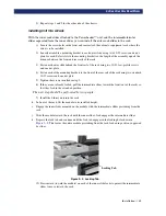
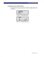
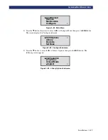
5) Suppose you want to set the Drive 1 bus ID to 3. With the
u
next to line 1, press the
q
button
until the display scrolls as shown in the following screen:
Figure 2–18. SCSI Options Submenu
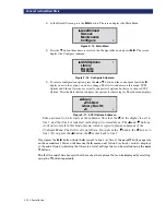
6) With the
u
next to line 3, press the
Enter
button. The
u
moves to line 4 and the
$$$$
remains at
the end of line 4, and a
####
displays at the end of line 1. Use the
p
and
q
buttons to scroll line 4
to display the possible settings. Scroll up so that 3 is displayed and press the
Enter
button to
save the new selection. An
✴
✴
✴
✴
displays to the left of the 3 indicating it as the current selection.
7) Press the
Escape
button repeatedly until the submenu reappears.
8) Repeat this procedure for each configuration option you want to change.
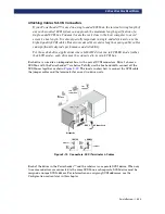
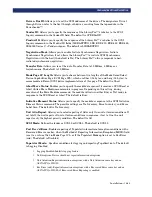
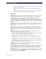
Configuring Multi-Module Systems
All PowerLoader™ modules are factory-shipped as stand-alone units meant to operate as
individuals. To include them in a multi-module system, you must first configure one
module as the master module and all other modules as slave modules. PowerLoader™
module can be configured to be a stand-alone, master, or slave module.
Master Module
The master module controls the operations of the multi-module system. Configuration
changes to the system are performed at the operator panel of the master module.
In a rack, the master module must occupy the top position to coordinate the action of the
Pass-Through Mechanism
.
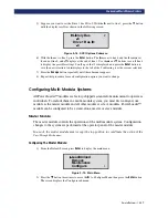
Configuring The Master Module:
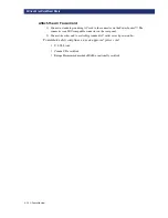
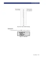
1) From the Default Screen, press
Enter
to display the main menu.
Figure 2–19. Main Menu
2) Press the
q
button three times to move the
u
to Configure Menu, then press the
Enter
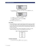
button.
The screen displays the Configure submenu:
u
Library Bus
✴
✴
✴
✴
6
Drive 1 Bus ID:
✴
✴
✴
✴
4
#
u
u
u
u
Load/Unload
Remove
Maintenance
Configure
$
Summary of Contents for PowerLoaders AIT-2
Page 1: ......
Page 4: ...ii u...
Page 13: ...xi LIST OF FIGURES CONT D...
Page 14: ...xii LIST OF FIGURES CONT D...
Page 16: ...xiv LIST OF TABLES CONT D...
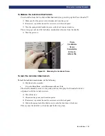
Page 26: ...2 2 u Installation RELEASING THE LOCKDOWN MECHANISM Lockdown Screw...
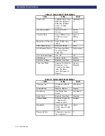
Page 52: ...2 28 u Installation CONFIGURATION OPTIONS DESCRIPTION...
Page 96: ...5 18 u Troubleshooting ERROR RECOVERY...
Page 102: ...A 6 u Specifications SPECIFICATIONS...
Page 104: ...B 2 u...


