background image

User Manual of Network Fisheye Camera


90 


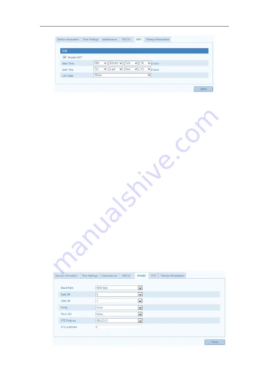
Figure 9-17


DST Settings 

9.10


RS-485 Settings 

Purpose: 

The  RS-485  serial port  is  used  to  control the  PTZ  of  the  camera.  The  configuring  of 

the PTZ parameters should be done before you control the PTZ unit. 

Note: 

RS-485 settings vary according to the camera model. 

Steps: 

1.


Enter RS-485 Port Setting interface: 

Configuration> Advanced Configuration> System > RS485   

2.


Set the RS-485 parameters. 

By default, the Baud Rate is set as 9600 bps, the Data Bit is 8, the stop bit is 1 

and the Parity and Flow Control is None. 

3.


Click 

Save

 to save the settings. 

Note:

 The Baud Rate, PTZ Protocol and PTZ Address parameters should be exactly the 

same as the PTZ camera parameters. 


Summary of Contents for C-OVE-6DVIR-FE

Page 1: ...Network Fisheye Camera User Manual...

Page 2: ...mprove or update the products or procedures described in the manual DISCLAIMER STATEMENT Underwriters Laboratories Inc UL has not tested the performance or reliability of the security or signaling asp...

Page 3: ...rence received including interference that may cause undesired operation EU Conformity Statement This product and if applicable the supplied accessories too are marked with CE and comply therefore wit...

Page 4: ...950 1 and Limited Power Source standard If the product does not work properly please contact your dealer or the nearest service center Never attempt to disassemble the camera yourself We shall not ass...

Page 5: ...romagnetic radiation To avoid heat accumulation good ventilation is required for a proper operating environment Keep the camera away from water and any liquid While shipping the camera should be packe...

Page 6: ...Recording and Capturing Pictures Manually 20 4 4 Operating e PTZ Control 21 4 4 1 e PTZ Control Panel 21 4 4 2 Setting Calling Deleting a Preset 22 4 4 3 Setting Calling Deleting a Patrol 24 Chapter...

Page 7: ...nfiguring Motion Detection 57 5 6 2 Configuring Video Tampering Alarm 61 5 6 3 Configuring Alarm Input 63 5 6 4 Configuring Alarm Output 63 5 6 5 Handling Exception 64 5 6 6 Configuring Line Crossing...

Page 8: ...Exporting Importing Configuration File 87 9 7 4 Upgrading the System 88 9 8 RS 232 Settings 88 9 9 DST Settings 89 9 10 RS 485 Settings 90 9 11 Fisheye Parameters 91 Appendix 92 Appendix 1 SADP Softwa...

Page 9: ...and above version Vista Win7 Server 2003 Server 2008 32bits CPU Intel Pentium IV 3 0 GHz or higher RAM 1G or higher Display 1024 768 resolution or higher Web Browser Internet Explorer 6 0 and above ve...

Page 10: ...camera via a LAN you need to connect the network camera in the same subnet with your computer and install the SADP or NVMS7000 software to search and change the IP of the network camera Note For the...

Page 11: ...in Figure 2 3 Use the NVMS7000 client software to list the online devices Please refer to the user manual of NVMS7000 client software for detailed information 2 Change the IP address and subnet mask...

Page 12: ...work camera to the WAN with a static IP or a dynamic IP 2 2 1 Static IP Connection Before you start Please apply a static IP from an ISP Internet Service Provider With the static IP address you can co...

Page 13: ...Visit the network camera through a web browser or the client software over the internet Figure 2 4 Accessing the Camera through Router with Static IP Connecting the network camera with static IP direc...

Page 14: ...e setting interface of the router 7 Visit the camera via the applied domain name Connecting the network camera via a modem Purpose This camera supports the PPPoE auto dial up function The camera gets...

Page 15: ...DDNS Settings for detailed configuration 3 Visit the camera via the applied domain name Private Domain Name Resolution Figure 2 8 Private Domain Name Resolution Steps 1 Install and run the IP Server s...

Page 16: ...nput the user name and password and click Login Figure 3 1 Login Interface Notes The default user name is admin and the default password is 12345 And you are required to change the initial password af...

Page 17: ...Figure 3 2 Download and Install Plug in Figure 3 3 Install Plug in 1 Figure 3 4 Install Plug in 2 Note You may have to close the web browser to install the plug in Please reopen the web browser and l...

Page 18: ...ew the live video and manage the camera with the software Follow the installation prompts to install the software The control panel interface of NVMS7000 client software is shown as bellow Figure 3 5...

Page 19: ...to enter the live view page or you can click Live View on the menu bar of the main page to enter the live view page Descriptions of the live view page Figure 4 1 Live View Page Menu Bar Click the tab...

Page 20: ...the close up view of some defined area in the Fisheye View or Panorama View and it supports the electronic PTZ function which is also called e PTZ Note Each PTZ View is marked on the Fisheye View and...

Page 21: ...el Start Stop live view Display the live video in full screen Enable Disable the two way audio Adjust the audio volume Manually capture the picture during live view Manually start stop recording Note...

Page 22: ...orts digital PTZ control also called e PTZ control function When PTZ View is selected for live view you can use the e PTZ control buttons to realize pan tilt zoom control of the PTZ View Figure 4 3 e...

Page 23: ...heye View and Panorama View 2 Click the direction arrows on the e PTZ control panel and the navigation box will move in the corresponding pan tilt direction 3 Click the icon to zoom in zoom out 4 Clic...

Page 24: ...from grey to black Figure 4 5 Setting a Preset Note Up to 256 presets are supported Calling a Preset Purpose The PTZ View of the Fisheye camera can directly and quickly move to the area of interest w...

Page 25: ...m the list 2 Click the icon to delete the selected preset The preset name turns from black to grey Figure 4 7 Deleting a Preset 4 4 3 Setting Calling Deleting a Patrol Purpose A patrol is a scanning t...

Page 26: ...ect a path No from the drop down list and click the icon in the lower left corner to add the presets as the key points Figure 4 9 Setting Key Point of Patrol 3 Select the defined preset from the drop...

Page 27: ...to select a PTZ View on the display window 2 Select the patrol path number from the drop down list 3 Click the icon to call the selected patrol path Deleting a Patrol 1 Select the patrol path number f...

Page 28: ...the local PC running the web browser Steps 1 Enter the Local Configuration interface Configuration Local Configuration Figure 5 1 Local Configuration Interface 2 Configure the following settings Live...

Page 29: ...mp Record File Settings Set the saving path of the recorded video files Valid for the record files you recorded with the web browser Record File Size Select the packed size of the manually recorded an...

Page 30: ...ettings Or Configuration Advanced Configuration System Time Settings Figure 5 2 Time Settings 2 Select the Time Zone of your location from the drop down list Synchronizing Time by NTP Server 1 Check t...

Page 31: ...time synchronization Synchronizing Time Manually 1 Check the Manual Time Sync item to enable the manual time synchronization function 2 Click the icon to open the calendar page 3 Click on the calenda...

Page 32: ...may be configured simultaneously without conflicting to each other and at least one IP version should be configured Steps 1 Enter TCP IP Settings interface Configuration Basic Configuration Network T...

Page 33: ...t 5 3 2 Configuring Port Settings Purpose You can set the port No of the camera e g HTTP port RTSP port and HTTPS port Steps 1 Enter the Port Settings interface Configuration Basic Configuration Netwo...

Page 34: ...5 7 PPPoE Settings 2 Check the Enable PPPoE checkbox to enable this feature 3 Enter User Name Password and Confirm password for PPPoE access Note The User Name and Password should be assigned by your...

Page 35: ...feature 3 Select DDNS Type Four DDNS types are selectable HiDDNS IPServer DynDNS and NO IP DynDNS Steps 1 Enter Server Address of DynDNS e g members dyndns org 2 In the Domain text field enter the do...

Page 36: ...from the ISP The Server Address should be entered with the static IP address of the computer that runs the IP Server software Figure 5 10 IPServer Settings Note For the US and Canada area you can ent...

Page 37: ...ss www hiddns com 3 Enter the Domain name of the camera The domain is the same with the device alias in the HiDDNS server 4 Click Save to save the new settings Note A reboot is required for the settin...

Page 38: ...t By setting the Trap Address the camera can send the alarm event and exception messages to the surveillance center Note The SNMP version you select should be the same as that of the SNMP software And...

Page 39: ...standard is supported by the network cameras and when the feature is enabled the camera data is secured and user authentication is needed when connecting the camera to the network protected by the IE...

Page 40: ...e the network delay and network congestion by configuring the priority of data sending Steps 1 Enter the QoS Settings interface Configuration Advanced Configuration Network QoS Figure 5 16 QoS Setting...

Page 41: ...to the Wide Area Network via the router Steps 1 Enter the UPnP settings interface Configuration Advanced Configuration Network UPnP 2 Check the checkbox to enable the UPnP function The name of the de...

Page 42: ...to Section 5 3 1 Configuring TCP IP Settings for detailed information 2 Enter the Email Settings interface Configuration Advanced Configuration Network Email Figure 5 18 Email Settings 3 Configure the...

Page 43: ...user Name and password Choose Receiver Select the receiver to which the email is sent Up to 2 receivers can be configured Receiver The name of the user to be notified Receiver s Address The email add...

Page 44: ...pshot task Steps 1 Enter the FTP Settings interface Configuration Advanced Configuration Network FTP Figure 5 20 FTP Settings 2 Configure the FTP settings and the user name and password are required f...

Page 45: ...pload the captured pictures to FTP server you have to enable the continuous snapshot or event triggered snapshot on Snapshot page For detailed information please refer to the Section 6 3 5 3 12Platfor...

Page 46: ...ber as 443 and the IP address is 192 0 0 64 you may access the device by inputting https 192 0 0 64 443 via the web browser Steps 1 Enter the HTTPS settings interface Configuration Advanced Configurat...

Page 47: ...grayed out Create the authorized certificate 1 Click Create button to create the certificate request 2 Download the certificate request and submit it to the trusted certificate authority for signature...

Page 48: ...is usually for recording and live view with good bandwidth and the sub stream can be used for live viewing when the bandwidth is limited 3 You can customize the following parameters for the selected...

Page 49: ...d Video Encoding If the Stream Type is set to main stream H 264 is selectable and if the stream type is set to sub stream H 264 and MJPEG are selectable Note The supported video encoding may differ ac...

Page 50: ...or ON When you set the function on the noise detected can be filtered 3 Click Save to save the settings Note The audio settings vary according to the camera model 5 4 3 Configuring ROI Encoding ROI s...

Page 51: ...Click the Draw Area button and then click and drag the mouse to draw the region of interest on the live video 6 Select the ROI level to set the image quality enhancing level The larger the value is t...

Page 52: ...lay parameters vary according to the different camera model Please refer to the actual interface for details Steps 1 Enter the Display Settings interface Configuration Basic Configuration Image Displa...

Page 53: ...colorfulness of the image color which ranges from 1 100 and the default value is 50 Sharpness describes the edge contrast of the image which ranges from 1 100 and the default value is 50 Exposure Sett...

Page 54: ...re selectable for IR mode Select AUTO and the IR LED changes according to the actual luminance E g if the current scene is bright enough then the IR LED adjusts itself to lower power and if the scene...

Page 55: ...Video Standard 50 Hz and 60 Hz are selectable Choose according to the different video standards normally 50 Hz for PAL standard and 60 Hz for NTSC standard Capture Mode It s the selectable video inpu...

Page 56: ...Black White Self adaptive and can also customize the color as desired 7 Click Save to save the settings 5 5 3 Configuring Text Overlay Purpose You can set the content of the text overlay and display...

Page 57: ...viewed and recorded Steps 1 Enter the Privacy Mask Settings interface Configuration Advanced Configuration Image Privacy Mask Figure 5 32 Privacy Mask Settings 2 Check the checkbox of Enable Privacy M...

Page 58: ...Center Send Email Trigger Alarm Output etc Note Check the checkbox of Notify Surveillance Center if you want to push the alarm information to the surveillance client such as the mobile phone computer...

Page 59: ...tion modes are selectable Normal mode and Expert mode Normal Mode If Normal is selected as the configuration mode one set of parameters are adopted for motion detection without considering the day nig...

Page 60: ...ht separately OFF Disable the day and night switch Auto Switch Switch the day and night mode according to the illumination automatically Scheduled Switch Switch to the day mode at 6 00 a m and switch...

Page 61: ...ou want to set the arming schedule 3 Click to set the time period for the arming schedule 4 Optional After you set the arming schedule you can copy the schedule to other days 5 Click OK to save the se...

Page 62: ...e when an alarm is triggered and upload the picture to a FTP server Note Set the FTP address and the remote FTP server first Refer to Section 5 3 11 for detailed information Trigger Channel The video...

Page 63: ...e video tampering detection function Figure 5 39 Video Tampering Detection Settings 3 Set the detection area for video tampering For details refer to Step 4 in Section 5 6 1 4 Click Edit to edit the a...

Page 64: ...refer to Step 5 in Section 5 6 1 4 Check the checkbox to select the linkage method taken for the alarm input For details refer to Step 6 in Section 5 6 1 5 Optional You can copy your settings to othe...

Page 65: ...lick Save to save the settings Figure 5 41 Alarm Output Settings Note Alarm output settings vary according to the camera model 5 6 5 Handling Exception The exception type can be HDD full HDD error net...

Page 66: ...displayed on each end and you can click and drag one of the red squares to define the shape and length of the line 5 Select the direction for line crossing detection And you can select the directions...

Page 67: ...or other objects which enter and loiter in a pre defined virtual region and some certain actions can be taken when the alarm is triggered Steps 1 Enter the Intrusion Detection settings interface Confi...

Page 68: ...s high a very small object can trigger the alarm Percentage Range 1 100 Percentage defines the ratio of the in region part of the object which can trigger the alarm For example if the percentage is se...

Page 69: ...re the recorded files log files etc Steps 1 Add the network disk 1 Enter the NAS Network Attached Storage Settings interface Configuration Advanced Configuration Storage NAS Figure 6 1 Add Network Dis...

Page 70: ...ializing the disk When the initialization completed the status of disk will become Normal Figure 6 3 View Disk Status 3 Define the quota for record and pictures 1 Input the quota percentage for pictur...

Page 71: ...cord Schedule Settings interface Configuration Advanced Configuration Storage Record Schedule Figure 6 5 Recording Schedule Interface 2 Check the checkbox of Enable Record Schedule to enable scheduled...

Page 72: ...then the recording will stop when the SD card or network disk becomes full Recording Stream Set the stream type for recording Main Stream and Sub Stream are selectable 4 Click Edit to edit the record...

Page 73: ...ideo will be recorded when the alarm is triggered via the external alarm input channels Besides configuring the recording schedule you have to set the Alarm Type and check the checkbox of Trigger Chan...

Page 74: ...d when the intrusion event is detected Besides configuring the recording schedule you have to set the intrusion detection area and check the checkbox of Trigger Channel in the Linkage Method of Intrus...

Page 75: ...g schedule for timing snapshot For details refer to Step 5 in Section 5 6 1 6 Click Save to save the settings 7 Optional To upload the captured pictures to the FTP server configure the FTP parameters...

Page 76: ...ure format resolution and quality for the snapshots 4 Set the time interval between two continuous snapshots 5 Set the capture number for each event triggered snapshot time 6 Click Save to save the se...

Page 77: ...stored in the network disks or SD cards Steps 1 Click Playback on the menu bar to enter playback interface Figure 7 1 Playback Interface 2 Select the date and click Search Figure 7 2 Search Video 3 C...

Page 78: ...es Select the playback mode Notes You can set the local file saving path for the downloaded video files and pictures in Local Configuration interface For details please refer to Section 5 1 Click the...

Page 79: ...User Manual of Network Fisheye Camera 78 Figure 7 5 Progress Bar Different video types are marked in different colors on the progress bar Figure 7 6 Video Types...

Page 80: ...he camera or insert a SD card in the camera Steps 1 Click Log on the menu bar to enter log searching interface Figure 8 1 Log Searching Interface 2 Set the log search conditions to specify the search...

Page 81: ...nter the Add User interface 2 Input the user name in the text field as desired 3 Input the password and confirm password for the user You can view the password strength from the page and it is recomme...

Page 82: ...r Steps 1 Click to select the user from the list and click Modify 2 Modify the User Name Level or Password 3 In the Basic Permission field and Camera Configuration field you can check or uncheck the p...

Page 83: ...Figure 9 4 RTSP Authentication 2 Select the Authentication type basic or disable in the drop down list to enable or disable the RTSP authentication Note If you disable the RTSP authentication anyone c...

Page 84: ...he anonymous visit 3 Click Save to save the settings There will be a checkbox of Anonymous by the next time you logging in Figure 9 6 Login Interface with an Anonymous Checkbox 4 Check the checkbox of...

Page 85: ...st Forbidden and Allowed are selectable 4 Set the IP Address Filter list Add an IP Address Steps 1 Click the Add to add an IP 2 Input the IP Adreess Figure 9 8 Add an IP 3 Click the OK to finish addin...

Page 86: ...rface Configuration Advanced Configuration Security Security Service 2 Check the checkbox of Enable Telnet to enable the remote login by the telnet and uncheck the checkbox to disable the telnet 3 Che...

Page 87: ...are displayed The information cannot be changed in this menu It is the reference for maintenance or modification in future Figure 9 11 Device Information 9 7 Maintenance 9 7 1 Rebooting the Camera Ste...

Page 88: ...tion File Purpose Configuration file is used for the batch configuration of the camera which can simplify the configuration steps when there are a lot of cameras needing configuring Steps Enter the Ma...

Page 89: ...rading process will take 1 to 10 minutes Please don t disconnect power of the camera during the process The camera reboots automatically after upgrading Figure 9 15 Remote Upgrade 9 8 RS 232 Settings...

Page 90: ...ould be exactly the same with the parameters you configured here 2 Click Save to save the settings 9 9 DST Settings Purpose For region using the summer time DST daylight saving time settings can be co...

Page 91: ...te RS 485 settings vary according to the camera model Steps 1 Enter RS 485 Port Setting interface Configuration Advanced Configuration System RS485 2 Set the RS 485 parameters By default the Baud Rate...

Page 92: ...Fisheye Parameters 2 Select the mounting type of the fisheye camera according to your actual environment and demand Ceiling mounting table mounting and wall mounting are selectable for the mounting ty...

Page 93: ...information of the devices using this software Search active devices online Search online devices automatically After launch the SADP software it automatically searches the online devices every 15 sec...

Page 94: ...the device table and hide the network parameter panel on the right side or click to show the network parameter panel Modify network parameters Steps 1 Select the device to be modified in the device l...

Page 95: ...User Manual of Network Fisheye Camera 94 Steps 1 Contact our technical engineers to get the serial code 2 Input the code in the Serial code field and click Confirm to restore the default password...

Page 96: ...Set the LAN parameters of the router as in the following figure including IP address and subnet mask settings Figure A 2 2 Set the LAN parameters 3 Set the port mapping in the virtual severs of Forwar...

Page 97: ...r the network camera at 192 168 1 23 2 Map the port 81 8001 555 and 8201 for the network camera at 192 168 1 24 3 Enable ALL or TCP protocols 4 Check the Enable checkbox and click Save Figure A 2 3 Po...

Reviews: