


Quick Installation Guide
FTD110DBMicro / version 2.0
OT Systems Ltd. | www.ot-systems.com
1
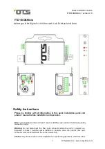
FTD110DBMicro
Microtype 8-bit Digital 1-ch Video with 1-ch Bi-directional Data
Safety Instructions
Please be familiar with all information in this quick installation guide and
product manual before installation and operation.
Note 1:
Each product contains a Class 1 laser or LED fiber optic emitter. The following safety
precautions apply.
Warning:
Do not disconnect the fiber optic connector while the unit is powered up.
Exposure to Class I invisible optical radiation is possible when the internal fiber optic
connector is disconnected while the unit is powered up.
Caution:
Any access to the controls, adjustments, or performing operations, which are other