One Stop Systems
OSS- BP-419 | 26
4
Verify Hardware
Verify all the LED indicators on the board and cards are properly illuminated.
4.1
Board Slot LEDs
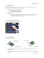
On the OSS-419 backplane, the following LEDs are illuminated as solid green.
SLT1: Slot 1
SLT2: Slot 2
UPSTR: Upstream Slot
4.2
Target & Host Cards LEDs
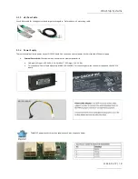
Check the LED indicators on both Target and Host cards. An operational host and target cards will have the following LEDs on the board
illuminated as green.
1.
PWR LED
2.
x4 CBL and EDGE LEDs
3.
x8 CBL and EDGE LEDs
4.3
LED Definition
PWR – Board has power
CBL – Signal detect on cable
*
EDGE – Signal detect on card edge
*
*
Signal detect does not mean it has a link, but rather it identifies there is a signal on the card edge. If the link does not appear to be stable, it
could mean that there is a compliance pattern being generated by the PCIe device interfacing with this card.
If the board is operating
on x4 mode
, x4 CBL and EDGE are only illuminated. This is indicative of a x4 slot PCIe slot (electrical) where the host or
target card is installed.


