background image

One Stop Systems 


4U Pro 16 Slot 


                                               58


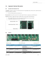
16.9.3  LED Indicator 


Summary of Contents for 4UP 16-SLOT GEN4

Page 1: ...INSTALLATION GUIDE 4UP 16 SLOT GEN4 4UP 16 SLOT Gen4 www onestopsystems com ...

Page 2: ... 6 Host Card Installation 20 6 1 Host Card Configuration 20 6 2 Switch Settings 22 7 GPU PCIe Cards Installation 23 7 1 Install PCIe card GPUs 24 7 2 Connect Aux Power Cables 24 7 3 Auxiliary Cable Management 25 8 Connect Link Cables 26 8 1 Mini SAS HD SFF 8644 Cable Installation 26 8 1 1 x16 Configuration FOUR cables 26 8 1 2 x8 Configuration TWO cables 27 8 1 3 x4 Configuration ONE cable 28 8 2 ...

Page 3: ...ate Mac Address IP Address 48 15 3 Start Internet browser 49 16 Important Technical Information 50 16 1 Upstream and Downstream Slots 50 16 2 Slot LEDs 50 16 3 Board LEDs 51 16 4 Slot Type 51 16 5 PS_ON 51 16 6 ARF6 Connector 52 16 7 Slot Number and Port Mapping 53 16 8 Power Cords 54 16 8 1 Specifications 54 16 8 2 Power cord socket and voltage tables world standards 54 16 9 Power Supply 55 16 9 ...

Page 4: ...8 17 1 Device is not detected or recognized 68 17 2 My PCIe devices are showing UP with a Yellow Exclamation mark 68 17 3 No link between host and target cards 68 17 4 Broken OSS Backplane 69 17 5 My PCIe cards are not detected 69 18 How to Get More Help 69 18 1 Contacting Technical Support 69 18 2 Returning Merchandise 69 18 3 Third Party Hardware Software Support Policy 70 18 4 Online Support Re...

Page 5: ...tream slot per backplane Linked Links two backplanes together so all slots are downstream to a single upstream Cooling Operational Temperature 0 35 C Operational Humidity 10 90 relative humidity Operational Altitude 0 10 000 feet above sea level Storage Temperature 40 C 71 C Fans 3x 180CFM 120mm fans Default PWM controlled based on built in temperature sensors Optional IPMI system monitoring and c...

Page 6: ...Features PCIe Gen4 architecture Semi rugged frame design Dynamic fan speed control Configurable slot and host uplinks to optimize throughput Integrated IPMI based system monitoring AC and DC power inlet options 1 2 4UP Architecture 16 Slot ...

Page 7: ...Pro 16 Slot 7 1 3 PCIe Slots Slot Type Closed ended PCIe slot connector all the slots are x16 mechanical Six x8 electrical slots slots 1 2 3 4 5 and 6 Three x16 electrical slots slots 0 7 and 8 1 4 Backplane Block Diagram ...

Page 8: ...One Stop Systems 4U Pro 16 Slot 8 1 5 Dimensions ...

Page 9: ...ED RJ45 Port Access to IPMI Front Panel Front Hand les Removab le Fans ARC Connectors Cables Target Cards Power Supplies Auxi iiary PowerConnectors IPM I Module Board Fan Power Connectors Power Supply Housing Backplane PCle Slot OSS 521 board Passive Heat sin k PCle Switch Number Number Number One Stop Systems 4U Pro 16 Slot 9 1 6 Parts Overview ...

Page 10: ...nnectors 19 Upstream Slots Target Slots 20 Downstream Slots PCle Card Slots Options Slots 19 19 Operates as either Downstream slot or Upstream slot depending on the slot 21 configuration 20 20 Number One Stop Systems 4U Pro 16 Slot 10 ...

Page 11: ...LED A single x4 SFF 8644 cable must be inserted into port 0 of the Target card On the Host card side you can plug in a single x4 cable to any port as long as the Host card switch is set to x4 mode When using two x4 SFF 8644 cables it must be connected to port 0 and port 1 of the Target card only On the Host card side plug in the two cables to port 0 and portt 1 OR port 2 and port 3 ...

Page 12: ...icator when slot is populated or not Solid green when card is present Off when no card 9 Target Slot LED LED status indicator for Target card Solid green when Gen 4 adapter card is installed 10 Upstream Port Target Slot Designated slot for Target card only 11 Dip Switches For slot configuration 12 Board LEDs LED status indicator for the board 13 FPGA Connector FPGA Programming connector 14 PS_ON E...

Page 13: ...Systems 4U Pro 16 Slot 13 1 9 Slot Configurations Configuration 1 Default slot configuration One Upstream slot and eight Downstream slots ARC6 cables are required and must be attached between the edge of the board and the slot connectors under the backplane Without those ARC6 cables nothing will work in SLOT 8 Configuration 2 Two Upstream slots Slot 0 and SLOT 8 with two partitions Slot 0 Partitio...

Page 14: ...1 Upstream Slot 15 Downstream slots 2 Non operational slots One Stop Systems 4U Pro 16 Slot 14 Configuration 3 Two backplanes are daisy chained together One Upstream slot and 15 Downstream slots ...

Page 15: ...wnstream slots 6 x8 slots Slot 1 2 3 4 5 and 6 2 x16 slots Slot 7 and 8 Configuration 2 OSS 521 backplane is linked to two host computers see diagram below Two partitions two Upstream slots Slot 0 and SLOT 8 with a total of 7 downstream slots Slot 0 Partition 1 with four Downstream slots o 4 x8 slots Slot 1 2 3 and 4 Slot 8 Partition 2 with three Downstream slots o 2 x8 slots Slot 5 and 6 o 1 x16 ...

Page 16: ...is linked to a single host computer With a total of 15 Downstream slots 1st backplane 7 downstream slots 6 x8 slots slot 1 2 3 4 5 and 6 1 x16 slot slot 7 One non operational slot slot 8 2nd backplane 8 downstream slots 6 x8 slots slot 1 2 3 4 5 and 6 2 x16 slots slot 0 and 7 One non operational slot slot 8 ...

Page 17: ...d have another card that is configured as host card b Check the dipswitches make sure it is set to host mode prior to installing the card 4 Install PCIe GPU cards a Plug in your PCIe or GPU cards in the expansion unit 5 Connect the external link cables a Plug in the Mini SAS HD SFF 8644 cables between Target and Host cards 6 Plug in the power cords a The unit is supplied power cord s You should ha...

Page 18: ...sis 2 Slide the enclosure cover towards the back of the unit to disengage it from the guides until it clears the back and then lift the cover off 5 Target Card Installation By default the Target cards are already in the unit See photos below for the correct slot location where the Target cards are installed ...

Page 19: ... sure to set the card switches to Target mode Find the SW1 on the card and set the switches to target mode see diagram photo below Move SW1 1 and SW 2 to ON position Once the card is configured install Target card in the designated target slot upstream slot Photo below shows the default location of the Upstream slots Make sure the card is firmly seated in the card slot and secured ...

Page 20: ... mode You can leave the switches to default or you can set the switches SW1 and SW2 on the card for the desired Host operating mode See Host Card Configuration section for more details 6 1 Host Card Configuration The following diagrams photos are the three switch settings for the Host card x16 Dip switch Settings SW1 2 ON 5 ON SW2 1 ON 2 ON x8 Dip switch Settings SW1 2 ON 5 ON SW2 1 OFF 2 ON or 2 ...

Page 21: ...mage the card during installation Align the host card PCIe connector on top of the PCIe slot and carefully push the card down until it is firmly seated Secure the card with the screw Below is a photo of a x16 PCIe slot connectors The photo on the right is a PCI E 3 0 x16 slot The specification of the PCIe slot is printed on the board next to connector for easy identification Use a x16 PCIe slot fo...

Page 22: ...EPROM WP off ON EEPROM WP on OFF CMI Power is NOT Supported ON Force Power ON OFF Host Mode ON Target Mode SWl 1111111111 SWl 5 must always be ON Auto mode not supported SW2 3 to 6 are not used Legacy backplane Magma Gen3 backplane Dip switches SWl SW2 OFF ON Plnl Mode ON ON Manual x16 ON OFF Not Used OFF ON Manual x8 x8 OFF OFF Manual x4 x4 x4 x4 3 to 6 Reserved SWl SW2 ...

Page 23: ...tream slots Slot 8 is an option slot It can be used either as an upstream or downstream slot depending on the slot configuration o Downstream mode Use downstream slot for an end point device i e video card Ethernet sound card and etc o Upstream mode Use upstream slot for an OSS Gen4 target card only IMPORTANT You need the ARC6 cables attached between the edge of the board and the slot connectors u...

Page 24: ...ver s prior to installing the hardware Install GPU card in the downstream slot one at a time Align the card on top of the slot Gently push the card down until it is firmly seated Secure the GPU or the PCIe cards 7 2 Connect Aux Power Cables Plug in the appropriate auxiliary power cable to each GPU Use the supplied compatible aux cable for your GPU Photos below is an example of an auxilirary power ...

Page 25: ...n board Perform the same installation methods for the remaining GPUs 7 3 Auxiliary Cable Management Route the cables away from the fan Make sure the cables are not blocking the air flow Use a zip ties or tie wraps to tuck the cables in You can also use a Velcro strap to hold or tie down the cables 0 Acceptable Cable Maoagemeot Poor Cable Management ...

Page 26: ... x4 mode connect one link cable See the following cable configurations for more details 8 1 1 x16 Configuration FOUR cables Plug in the 1st cable to Port 0 Top port on both Target and Host cards Plug in the 2nd cable to Port 1 on both Target and Host cards Plug in the 3rd cable to Port 2 on both Target and Host cards Plug in the 4th cable to Port 3 Bottom port on both Target and Host cards Note It...

Page 27: ...he two cables to the bottom ports 1st Cable to PORT 2 2nd cable to PORT 3 Note The two cables on the TARGET card must remain connected on PORT 0 and PORT 1 See diagrams below as an example Photo B1 The two cables are connected on the Target card PORTS 0 and 1 The other end of the cables are connected on the Host card PORTS 2 and 3 Photo B2 The two cables are connected on the Target card PORTS 0 an...

Page 28: ...onnected on Target card PORT 0 Photo A1 Cable stays connected on the Target card PORT 0 The other end of the cable is connected on the Host card PORT 1 Photo B1 Cable stays connected on the Target card PORT 0 The other end of the cable is connected on the Host card PORT 2 Photo C1 Cable stays connected on the Target card PORT 0 The other end of the cable is connected on the Host card PORT 3 Target...

Page 29: ...cting Mini SAS HD SFF 8644 Cable To disconnect the link cable pull back the PLASTIC thumb tab to release metal clamp while slowly pulling the cable out Host Card Target Card Host Card Target Card OR Port 0 SFF 8644 cable SFF 8644cable Port l Host Card Target Card Host Card Target Card OR Port 2 Port 3 ...

Page 30: ...Ensure that the system s power supply unit is fully secured before connecting the power cord You should have either the 125v or the 250v power cord If you only have the 125V power cord and you require the 250V power cord please contact our Sales Team sales onestopsystems com to place an order Power Cord Voltage Table Power Cord PSU Watt Voltage AMPS Hz 125V 1000W 100 127V 12 9 5A 50 60Hz 250V 1800...

Page 31: ... LED PSU Good Amber LED PSU fault or power issue If Power LED indicator is showing Amber in color it indicates a fault or power issue The two front LEDs the OSS logo will illuminate as blue and the STANDBY MAIN PWR will come ON as solid green ...

Page 32: ...n a x16 Gen3 Gen4 PCIe slot and the cables are firmly connected Upon powering up the Host computer it will initialize a link between the target and the host The Link LED on both target and host cards will illuminate as solid green Solid green Link LED it means the negotiated link width between host and target card is x16 Blinking green Link LED the link width is x8 ...

Page 33: ... LED when a PCIe card is installed in the target slot the LED will illuminate as solid green A fully operational back plane will illuminate the following LEDs Check LEDs D19 D18 and D16 make sure they are correctly illuminated D19 Blinking green LED 1 D18 Solid green LED 0 D16 AUX power solid green ...

Page 34: ...rror FE Fatal Error LED Solid Red Hardware fa il ure Backplane need service or repair D20 CONFIG LED Solid Red Board is not programmed Firmware corrupted Need to send back to manufacturing for service or repair RED LED CR3 PEDRT The backplane is not getting initialized due to Faulty Target ca rd Board is not programmed ...

Page 35: ...en D4 LED1 Solid green D6 LED2 Solid green D8 LED3 Solid green CHO Link LED Solid green C9 Aux Power Solid green x16 configuration Four x4 Cables connected CHO LED will illuminate as solid green indicates of a stable LINK between Target and Host cards When there is no link between Target and Host cards the CHO LED is turned OFF The C9 Aux power LED will illuminate as solid green which is an indica...

Page 36: ... installed LED Status Description CHO Dl ON Solid Green Link LED Indicates a connectivity between OSS Host and Target cards LEDO D2 ON Solid Green Power Good LED1 D4 ON Solid Green Power Good LED2 D6 ON Solid Green Power Good LED3 D8 ON Solid Green Power Good CE D11 ON Solid Green Solid Green The CARD EDGE connector is communicating to Gen4 PCle switch on the host computer motherboard Blinking Gre...

Page 37: ... the PSU is working properly See photos below for the location of the PSU DC GOOD led 11 7 Front LED There are three visible LEDs located on the front of the unit The LOGO led will illuminate as solid BLUE Standby MAIN PWR Solid green when unit is fully powered ON Red when the unit is on standby mode IPMI This is optional Will only illuminate as solid green when IPMI module is installed in the uni...

Page 38: ...the LED should be amber During protection mode 5Vsb rail the LED should be OFF When protection is cleared the LED should go back to the original intended status When the unit is on standby with AC is present the LED should be amber When the unit is on standby with no AC is present the LED should be OFF When the unit is turned ON properly the LED is green During wakeup redundancy mode the LED shoul...

Page 39: ...ems 4UP expansion unit requires no driver on Windows 7 Windows 8 Windows 10 Windows Server Linux Unix Centos and Mac OS Before attempting to install anything on a Windows system you should ensure that you have set a Restore Point that all data files are closed and that you have a current backup of your data ...

Page 40: ...ng one device the host card is not linking up with the target device If there are two devices detected it is an indication that the backplane is not recognized You can also run lspci m grep Device 00b2 Three instances of 00b2 signify that both host targets cards including the backplane are correctly detected If one instance of 00b2 is showing up only the Host card is detected the Target and backpl...

Page 41: ...put below shows that the operating system is recognizing the OSS Host card Target card and backplane The output below shows that the operating system is only detecting the Host card No link between Target card and Host card File Edit View Bookma rks Settings Help ...

Page 42: ... cont inef Raourca by type Resources by conncctJOn Showhtddcndcwa CustOfflltt File Action View Help Windows Device Manager etface forACPI ch Pon ch Port s ntchPort mSwcch Poft PCI Express Downstream Switch Port PCIExpress Upstream Switch Port PCI Express Downstream Switch Port PCI Express Upstream Switch Port PCIExpress Downstream Switch Port PCIExpress Downstream Switch Port PCI Express Upstream ...

Page 43: ... CD ROM drives liml X Windows Device Manager on Windows Server 2012 R2 _ Oiikdrives DKplay 1d 1ptffl Hum n lnttrf u Devices IOEATA ATAPI controllm _ Keytx rds i Mice and other pointing devices Moniton ft Multifunction adapters Print queues C Pr0 e ssors I Softwo1rt dtvice s Sound vidto 1nd gaMt controllers Storage controllers S emdevices ACPI fbced Feature Button AMO GPIO Controller AMD PCI AMDPCI...

Page 44: ... the terminal window lspci vtt command Output below is a screenshot of the lspci vtt showing the OSS backplane with seven cards that are detected You can also grep the vendor name of the PCIe card For example if you have an NVIDIA GPUs run the command on the terminal window lspci vvv grep NVIDIA Screenshot below shows one ATTO PCIe card is detected in slot 7 7 PCle cards detected One PCle card det...

Page 45: ...oaded You can obtain the driver from the card manufacturer or you can download it from the vendor s website OSS does not provide 3rd party driver software Computer Management loca fl System Tools t Task Scheduler Event Viewer Shared Felde rs local Use rs and Groups Performance Device Manager Storage t Windows Server Backu Disk Management t a Services and Applications PCIstandard PCl to PCIbridoe W...

Page 46: ... PCI Exprns Upru m Switch Port PCIExp1ess Oownstrum Switch Port PCIExpress Upstrum Switch Port PCIExpress Oownst1um Switch Port PCIExpress Oownstrum Switch Port PCIExp1ess Upstrum Switch Port PCIExpress Downst um Switch Port PCI Exp1ess Downstre m Switch Port J E thernet Controller i Ethernet Controller PCIExpress Downstre m Switch Port PCIExpress Downstrum Switch Port PCIExprns Oownstrum Switch P...

Page 47: ...ms com Unit equipped with IPMI below photo shows the location of IPMI module installed in the unit How to setup and access IPMI follow instructions below 15 1 Connect Ethernet Cables 1 Connect Ethernet cable to either front or back Ethernet port you can only use one or the other You must plug in the Ethernet cable first before you connect the power to the unit 2 Plug in the other end of the Ethern...

Page 48: ... Mac address The photo below shows the location of the label with the Mac address numbers There are two Mac addresses one for each port Below photo shows thirteen characters 00184904C9E8 9 The last digit is the designated number for the Ethernet port location on the unit Based on the photo below number 8 is for the back end Ethernet port The last number 9 is for the front end Ethernet port The num...

Page 49: ...lane temperature 3 Power supply voltage and temperature PS C WINDOWS system32 Get NetNeighbor ifindex IPAddress 7 192 168 1 153 00 18 49 04 cl 2c LinklayerAddress 00 18 49 04 Cl 2 PS C WINDOWS system32 2c is the Mac address for the back ethernet port ass I I ONE STOP SYSTEMS ADM 1026 Intern al Temperature Sensor 21C Fan 1 Status OK Fan 1 Speed 5100RPM 3V3 STBY Voltage 3 3V 3V3 MAIN Voltage 3 3V 5V...

Page 50: ...ownstream mode will only work with an end point device or a 3rd party PCIe card Configured as an Upstream mode use only an OSS HIB Target card 16 2 Slot LEDs Item Name Description When Lit Solid Green or Blinking When Off 1 Target Slot LED Upstream Slot LED Solid Gen4 Link OFF Not Linked No Card present in the slot Blink 2Hz Gen3 Link Blink 1Hz Gen2 Link Blink 0 5Hz Gen1 Link Slow Blinking 2 Downs...

Page 51: ...tput from the FPGA but enabled as an FPGA option When RED board is not programmed OFF board is programmed 16 4 Slot Type Slot Type Closed ended PCIe slot connector x16 mechanical Six x8 electrical slots slots 1 2 3 4 5 and 6 Three x16 electrical slots slots 0 7 and 8 16 5 PS_ON The board has a two pin connector for placing a shunt jumper that allows the backplane to be ON all the time when an ATX ...

Page 52: ...e Stop Systems 4U Pro 16 Slot 52 16 6 ARF6 Connector ARF6 Connector For connecting ARC6 cable to daisy chain two backplanes together and to create a bridge or connection between SLOT 8 and the PCIe switch ...

Page 53: ... the backplane PCIe port 56 will be automatically assigned to the card Port Slot Slot Mapping 88096 Port Slot 0 0 Slot 1 48 Slot 2 56 Slot 3 64 Slot 4 72 Slot 5 80 Slot 6 88 Slot 7 32 Slot 8 16 Daisy chain If slot 8 is cabled to the daisy chain port it becomes port 16 of the 88096 regardless of upstream downstream configuration NA If not enabled no port assignment Port 0 Slot 0 Port 16 Slot 8 Port...

Page 54: ... Conductors 3 Cord Type SJT Wire Gauge 14 AWG Shielding Unshielded Approval Marks CSA UL Approved Countries Canada USA Voltage Rating 125V Current Rating 15A Operating Temperature 60 C Digi Key Part Q944 ND Part Status Active Style Male pins Blades to Female Sockets slots 1st Connector IEC 320 C14 2ND Connector IEC 320 C13 Number of Conductors 3 Cord Type SJT Wire Gauge 14 AWG Shielding Approval M...

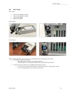
Page 55: ...C power supply modules ea 1600 W With two power supply modules installed o Share the power load requirements during normal operations o Should one module fail for any reason the power load will be shifted to the other module LED indicator to keep you informed on normal abnormal conditions for your PSU o An indicator for the failure would be the LEDs on the back panel of the power supply behind the...

Page 56: ...Slot 56 16 9 1 Removing AC Power Supply 1 Disconnect the power cord from the power supply you are removing 2 Grasp the power supply handle 3 Press the black release latch upward and hold it 4 Pull the power supply out of the bay ...

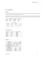
Page 57: ... Parameter Minimum lnput Rated Input Maximum Input 115Vac 90Vac 100 127Vac 140Vac 230Vac 180Vac 200 240Vac 264Vac Frequency 47Hz 50 60Hz 63Hz 240VDC Input Rating PARAMETER MIN RATED MAX Voltage 192VDC 240VDC 288VDC Current JOA 8 5A Input Voltage Input Current Maximum Power 90Vac 15A lOOOW 100 127Vac 13 lOA lOOOW 140Vac 9A IOOOW 180Vac II SA 1600W 200 240Vac 10 8 SA 1600W 264Vac 7 5A 1600W GROUP I ...

Page 58: ... in the Cold GREEN Redundancy section of the CRPS Common Requirements Specification AC cord unplugged or AC power lost with a AMBER second power supply in parallel still with AC input power Power supply critical event causing a AMBER shutdown failure over current short circuit over voltage fan failure over temperature Power supply warning events where the power IHz Blink supply continues to operat...

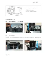
Page 59: ...0 1 Fan Specifications Series PFR Power Watts 44 40W Part Status Active RPM 11500RPM Voltage Rated 12VOC Termination 4 Wire Leads Size I D1 mens1on Square 92mm L X 92mm H Ingress Protection Width 38 00mm Operating Temperature 1o 70 C Air Flow 185 55CFM 5 255 m3 min Weight gram g 260g Static Pressure 2 523inchH2O 64 1 0mmH2O Current Rating 3 70A Bearing Type Ball Voltage Rating 07 0 13 2VDC Fan Typ...

Page 60: ...rs with minimal airflow resistance to prevent dust from entering the expansion unit You can easily remove and clean the filter To access the foam air filter simply remove the fan first and pull the filter out see photos below 3 622 0 020 82 5 0 J 3 248 0 012 355 0 10 0 13 189 0 394 Unit mm inch LEAD WIRE UL 1061 F AWG 22 Black Wire Negative Red Wire Positive Blue Wire Frequency FOO Yellow Wire Spe...

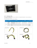
Page 61: ...90 010 037 RC 01 Cable Assy Aux Pwr 8 Pin NVIDIA 2 0 12 Expansion System M176 OSS 8 pin male to 8 pin male One 8 pin connector 290 010 037 RC 02 Cable Assy Aux Pwr 8 Pin NVIDIA 2 0 24 Expansion System M176 OSS 8 pin male to 8 pin male One 8 pin connector 6 2 pin 290 010 013 RC Cable Assy Canister External Pwr Dual 6 2 PCIe Graphics Only 8 pin male to 2 6 2 pin male Two 6 2 pin connectors 290 010 0...

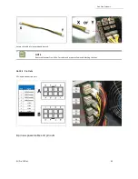
Page 62: ...ons ports in which the auxiliary power cables are plugged in see photo below To plug in the 6 2 pin cable correctly connect the Y end connector of the cable to the power distribution board see photos below To plug in the 8 pin cable correctly you can use either X or Y end of the cable see photos below Connectors Can provide powerof 8 pin 150 Watts Two 6 2 pin 300 Watts 6 pin 75 Watts X ...

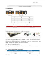
Page 63: ...d secured NOTE Route cables away from FANs For safety and proper airflow avoid blocking the fans 16 12 2 Pin Outs PSU board aux port pin outs 8 pin aux power cable and pin outs X El 8 7 6 5 A GND Ground 2 GND Ground 3 GND Ground 4 3 2 4 GND Ground 5 12V 6 12V z i 7 12V 8 12V B s 9 L 8 ...

Page 64: ...ble 8 pin male to 2 6 2 pin male Figure Al 6 2 pin connector Yellow 12V 5 6 7 8 Plastic Bridge 2 Yellow 12V Yellow 12V 4 Black GND Black GND Black GND Black GND 2 3 4 Front view 6 2 pin aux cable 8 pin male to 2 6 2 pin male FigureA2 8 pin connector Black GND 5 6 7 8 2 Black GND 3 Black GND 4 Black GND 5 Yellow 12V 6 Yellow 12V 7 Yellow 12V 2 3 4 Front view ...

Page 65: ... consumption A direct connection to the power system is needed to obtain additional power This can be done by using the 6 2 pin or 8 pin auxiliary power cables The below photos represent how the 6 2 pin connector and 8 pin aux power cables are attached to the PCIe card or GPU card The photo below is an example of a PCIe card or GPU card that has two 6 pin power connectors 8 pin aux cable 8 pin mal...

Page 66: ...connectors PCI Express x16 Graphics 150 W ATX Specification Published in October 2004 this standard defines a six pin 2x3 auxiliary power connector capable of delivering an additional 75 W to a graphics card directly from the power supply for a total of 150 W to the card PCI Express 225 W 300 W High Power Card Electromechanical Specification Published in March 2008 this standard defines an eight p...

Page 67: ...the wrong power cable to use due to special keying on the eight pin connector The GPU power connector has a different keying to prevent interchanging with the 12 V power connectors NOTE We do not provide different aux power cables i e 8pin to 4pin Molex other than what we offer If your PCIe card requires a different power adapter or aux power cable you would have to buy it from other electronic st...

Page 68: ...eboot the system after installing the driver 17 3 No link between host and target cards 1 Check the dipswitches on each card Make sure the Target card is set to target mode and Host card is set to host mode 2 Check the Target card is installed in the target slot upstream slot 3 Use a validated certified OSS HIB Cable adapter Gen4 cards 4 Reseat the Cables Makes sure you are using a Gen4 cables 5 S...

Page 69: ... Ticket or Case if you already submitted an online request 3 Computer Type Model Operating System 4 Make Model of PCI PCIe cards Application 5 Problem description When submitting an online technical support request always provide a valid working e mail address phone number shipping address and proper contact name Check your e mail for an automated response containing the case and updates You can a...

Page 70: ...tomer innovation by combining OSS products in new and interesting ways with third party and customer developed hardware and software Unfortunately with virtually infinite combinations of hardware and software OSS cannot test and validate every possible configuration OSS is committed to supporting its products and identifying if any technical issue may be related to third party hardware or software...

Page 71: ...One Stop Systems 4U Pro 16 Slot 71 ass ONE STOP SYSTEMS 2235 Enterprise Street Suite llO Escondido CA 92029 Toll Free 1 800 285 8900 US Main l 760 745 9883 Fax l 760 745 9824 www onestopsystems com ...

Reviews: