background image

8

SHARPY X FRAME

Locking and releasing Pan and Tilt movements - Refer to the instructions in the UNPACKING AND PREPARATION section.
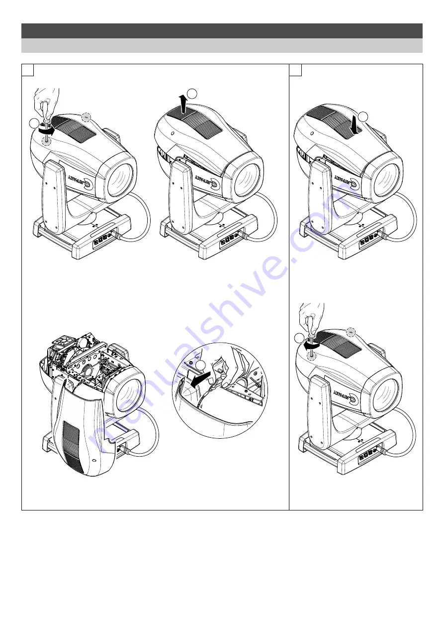
Opening the head covers - Fig. 11.

Closing the head covers - Fig. 12.

1

1/4 Turn

2

1

2

1/4 Turn

3

11

12

4.  MAINTENANCE

4.1 Opening the covers

Summary of Contents for CD3003

Page 1: ...nts INDEX ENGLISH Page Contents 2 1 Safety information 3 2 Unpacking and preparation 4 3 Installation and start up 4 3 1 Installing the fixture 5 3 2 Connecting to manis supply 5 3 3 Connecting the co...

Page 2: ...rmationen bez glich dieses Produkts genau zu lesen und aufzubewahren Sie sind in Digitalversion immer unter folgendem Link auffindbar www claypaky com Ref FIS027 Safety Information Sharpy X Frame INFO...

Page 3: ...anism Lock and Release every 90 Fig 2 TILT Mechanism Lock and Release every 45 Fig 3 Packing contents Fig 1 90 9 0 9 0 9 0 UNLOCKED LOCKED 4 5 4 5 45 4 5 45 4 5 4 5 LOCKED UNLOCKED 2 x 183102 805 2 UN...

Page 4: ...NG with the exception of when the projector is positioned on the floor the safety cable must be fitted Cod 105041 003 available on request This must be securely fixed to the support structure of the p...

Page 5: ...cable or other cable with characteristics differing from those specified The end connections must be made using XLR type 5 pin male female connectors A terminating plug must be inserted into the last...

Page 6: ...etting status after a wait time about 30 seconds without any key having been pressed the display automatically returns to rest status It should be noted than when this condition occurs any possible va...

Page 7: ...ions Option Option Menu To set the operating options Informations Informations Menu To read the counters software version and other information Manual Control Manual control Menu To trigger the test a...

Page 8: ...leasing Pan and Tilt movements Refer to the instructions in the UNPACKING AND PREPARATION section Opening the head covers Fig 11 Closing the head covers Fig 12 1 1 4 Turn 2 1 2 1 4 Turn 3 11 12 4 MAIN...

Page 9: ...the reflectors from the lenses and filters It is recommended that the projector undergoes an annual service by a qualified technician for special maintenance involving at least the following operatio...

Page 10: ...ffect modules Fig 14 IMPORTANT Grasp the modules using the support structure and not the details which could get damaged Insertion of the effect modules Repeat the operations indicated in Fig 14 15 an...

Page 11: ...of the effect modules Fig 15 IMPORTANT Grasp the modules using the support structure and not the details which could get damaged Insertion of the effect modules Repeat the operations indicated in Fig...

Page 12: ...12 SHARPY X FRAME 1 2 16 Cleaning of the grids Fig 16...

Page 13: ...gure WARNING The lamp must be adjusted with the projector switched off After adjusting close the effects covers switch on the projector and check that the adjustment has been correctly made If necessa...

Page 14: ...ng group replacement Fig 18 18 4 4 Rotating gobos GOBO DI VETRO DICROICI TIPO 1 GOBO DI VETRO DICROICI TIPO 2 To determine which side of a godo is coated hold an odject up to it On the uncoated side t...

Page 15: ...15 SHARPY X FRAME This product contains a rechargeable battery To preserve the environment please dispose the battery at the end of its life according to the regulation in force 21 4 5 Battery removal...

Page 16: ...al transmission cable faulty or disconnected Incorrect addressing Fault in the electronic circuits Lenses broken Dust or grease deposited Check the power supply voltage Call an authorised technician R...

Reviews: