background image


Osprey Video    


68 


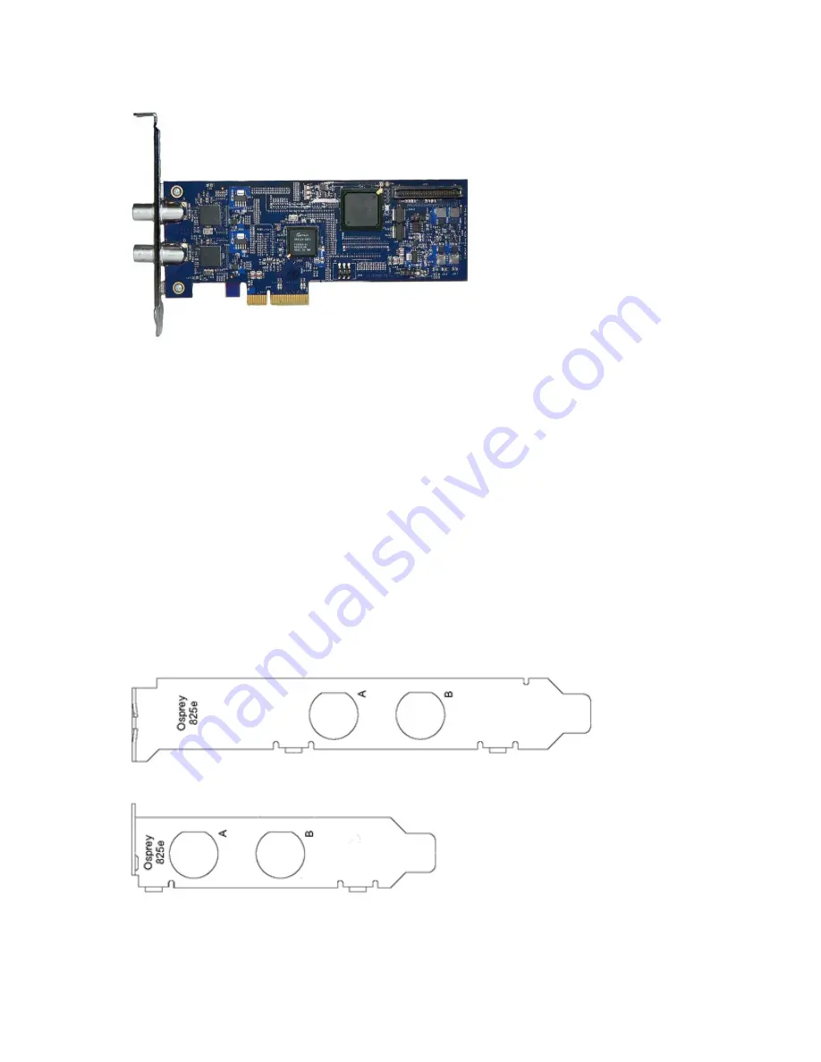
Osprey 825e video capture card


Environmental specifications 


Operating temperature range   0° to 40° C  

Non-operating temperature range   -40° to +75° C  

Operating humidity range   Between 5 % and 80 % 

(noncondensing) @ 40° C  

Non-operating humidity range   95 % RH (non-condensing); gradient  

30 % per hour  

Operating altitude range   0 to 3,048 meters (10,000 feet)  

Non-operating altitude range   0 to 15,240 meters (50,000 feet)  


• 

PCI Express (x4) card compliant 


• 

Approximate weight: Osprey 825e = 70 grams 


Figure 57. Osprey 825e full-height backplate  


Figure 58. Osprey 825e half-height backplate  


Summary of Contents for 800e Series

Page 1: ...Osprey 800e Series User Guide Osprey Video 1 ...

Page 2: ...n a residential installation This equipment generates uses and can radiate radio frequency energy and if not installed and used in accordance with the instructions may cause harmful interference to radio communications However there is no guarantee that interference will not occur in a particular installation If this device does cause harmful interference to radio or television reception the user ...

Page 3: ...s 18 Setting Driver Properties 20 Properties window 20 Video Proc Amp tab 23 Video Decoder tab 25 Crossbar tab 27 Trace tab 28 Performance tab 29 Diagnostics tab 31 Resource Monitor tab 32 Device tab 34 Input Detect tab 35 Deinterlace tab 36 Watermark tab 38 Loss Of Signal tab 41 Cropping tab 43 Closed Caption tab 46 VGA Settings tab 48 Understanding Audio Input Properties 50 Audio Properties page...

Page 4: ... 800e Series User Guide Osprey Video 4 Osprey 815e video capture card 65 Osprey 820e video capture card 66 Osprey 821e video capture card 67 Osprey 825e video capture card 68 Osprey 845e video capture card 69 ...

Page 5: ...following Limited Warranty Osprey Video warrants its hardware products against defects in material and workmanship under normal use for the period of one year 12 months from date of sale Where specific Osprey Video warranties exist that provide more substantial coverage notwithstanding the warranty provisions herein such product warranties control and preempt or supersede the warranty provisions h...

Page 6: ...essor per HD input is a good benchmark Please refer to the website for the latest supported operating systems Other important guidelines include On the BIOS screen o Always disable C States o Only enable hyper threading if the CPUs have 6 cores or more Set Power Options as follows o Power Scheme to Presentation o Turn off Monitor to Never o Turn off hard disks to Never o System Standby to Never Co...

Page 7: ...system for the first time After the install is run the card is detected and its drivers automatically start Note Before you install Osprey software updates uninstall the driver software and reboot the computer Installing the driver via the Multimedia CD 1 Insert the Osprey software CD in the CDRom drive of the computer If autoplay is enabled the main menu for the Osprey software CD automatically a...

Page 8: ...ent 5 Click Next A Destination Folder window appears indicating the folder in which the driver will be installed by default To change the location of the destination folder click Change to browse for a different location If this destination folder is okay click Next Figure 3 Destination Folder window The Setup Type window appears ...

Page 9: ...window The Installing Osprey 800e window appears Note This window shows the progress of the installation If during the installation warning windows appear regarding Windows Logo Testing the user should click Continue Anyway to proceed with the installation Figure 5 Installing Osprey 800e HDx86 window ...

Page 10: ...e Installation window Note This window does not display with a Windows 7 installation 7 Click Finish when the InstallShield Wizard Completed window appears 8 When the installation is complete completely shut down the computer on which the driver has been installed ...

Page 11: ...ars and guides you through the installation process 1 A Welcome window appears Click No not this time Figure 7 Welcome window 2 Click Next 3 On the next window click Install the software automatically Recommended Figure 8 Install Software Automatically window Note The device name will vary depending on which card you are installing 4 Click Next The installation begins and the Found New Hardware Wi...

Page 12: ...rd window A warning window appears regarding Windows Logo Testing 5 Click Continue Anyway Figure 10 Warning window The Found New Hardware Wizard window remains on the computer screen while the installation continues Note This window does not display with a Windows 7 installation ...

Page 13: ... 800e Series User Guide Osprey Video 13 Figure 11 Found New Hardware Wizard window 6 The Completing the Found New Hardware Wizard appears Click Finish Figure 12 Completing the Found New Hardware Wizard window ...

Page 14: ... the system s documentation for more complete step by step instructions Install the card only in UL Listed computers that include instructions for user installed accessories 1 Power down and unplug your computer 2 Remove the computer s cover and locate an empty PCI Express slot WARNING Be sure to install the card in the PCI Express slot This slot is usually black Refer to the following diagram as ...

Page 15: ...l the driver installation package for the new board to work B You moved a board from one slot to another or added another board of the same type For example an Osprey 240e card is installed in the computer and you want to install another Osprey 240e card In this case the following sequence takes place 1 The New Hardware Wizard runs and the Found New Hardware window appears followed by the Digital ...

Page 16: ...aptions With the Osprey 800 series all the above features can be set individually Each application receives its own full set of identical Property settings tabs Another significant operational difference of the Osprey 800 series and other Osprey cards is that in the Osprey 800e series each stream is configured separately As a result the second and subsequent streams may appear to have randomly cha...

Page 17: ... the most popular applications of the Osprey digital HD capture cards is to accept SD and HD input for live Internet video streaming Generally the expected viewing experience is for the viewing window to have fixed dimensions regardless of the aspect ratio or pixel count of the incoming video Most of the popular video encoders require that these parameters not change during the encoding session Th...

Page 18: ...usually use the Preview pin In most cases the Preview pin has a lower priority in the video processing engine If the host PC is nearing its upper performance margin where video quality could be compromised it is preferable to sacrifice quality or drop frames in the Preview output in favor of sustaining quality of the Capture pin s output Exposing these pins separately in Osprey drivers allows you ...

Page 19: ...saturation and sharpness controls the graphical gamma control and the graphical sizing and positioning controls for logos OK Cancel and Apply have no effect on these controls In all cases Help accesses the help module Note OK and Apply commit only the changes on the currently displayed page To set changes on three different pages you need to click Apply twice and OK once ...

Page 20: ...vers Property tabs without modification so the examples set forth below will probably appear as shown However some applications expose the Property tabs slightly differently Therefore the examples below may differ somewhat Properties window When your video application such as WME is invited to expose the Osprey 800 series card s video related property pages usually by navigating to the Properties ...

Page 21: ...e Crossbar tab lets you select from multiple inputs Trace Sets error logging controls Performance Sets the pin centric settings Diagnostics Sets Osprey 800 series internal test controls The user should only use these controls when instructed by Osprey support Doing so without proper instructions might result in system instability or in the system crashing Resource Monitor Displays PCIe states and ...

Page 22: ... listed above may appear The additional tabs are application or system supplied and are intended for information only The additional tabs generally contain no controls that can be changed Note Some controls are interactive For example changes you make are updated immediately in the captured video Such examples are the Brightness Contract Hue and Saturation controls graphical Gamma control and grap...

Page 23: ... When video is captured through a camera the response of the camera is deliberately nonlinear low lumen values are boosted and high lumen values are compressed This process is done for two reasons It increases the effective bandwidth in the low lumen range where it is needed at the expense of the high lumen range where it is needed less It matches the response characteristics of TV sets and monito...

Page 24: ...tion The Hue slider is disabled when PAL is selected All slider values are applied real time For example if Preview or real time capture to screen video is running when you access the Preview tab you can see adjustments as you make changes Individual Restore buttons return the respective slider to the settings as set when the dialog box is opened An adjustment scale is also included to identify ea...

Page 25: ...dards Osprey 800 series Osprey 820e only NTSC HD 1035 PAL 483 HD 720 VGA HD 1080 SECAM The selection should be set to match the incoming signal s primary mode Although the Osprey 800 series board automatically senses and adjusts to incoming signals including switching between SD and HD modes setting the incoming signal s primary mode is advisable to avoid the slight delay that results from evaluat...

Page 26: ...eo to be Whatever you select here displays on other tabs in the Reference Size text boxes Once you make the selection on the Video Decoder tab you must go to the other tabs Watermark or Cropping and click the Reset Reference button so the Reference Size text box is updated to the size corresponding to that chosen on the Video Decoder tab Detected Format This field lists the detected format ...

Page 27: ...r tab Use the Crossbar tab Figure 18 to set the input and output settings Figure 18 Crossbar tab The Crossbar tab has the following controls Input Click on the input source from the drop down list Output Click on the output source from the drop down list ...

Page 28: ...ettings are normally disabled An authorized Osprey support representative may ask you to change these settings should you experience problems using the Osprey 800 series with a video application The selection that is enabled is added to the time log Figure 19 Trace tab WARNING Leaving the Log file enabled can result in a large file that consumes all available disk space ...

Page 29: ...Type The drop down list has three choices see Capture and preview pins Video Scaling Algorithm Select the video scaling algorithm from the drop down menu Note Cubic and Lanczos are CPU intensive and are not recommended for high definition Default Video Input Size Select the default video input size from the drop down menu to scale the incoming video Note These values are only used if the applicati...

Page 30: ...e application does not explicitly request a specific resolution Input pin mode Displays the input port setting Remove VBI lines from video Indicate the number of VBI lines that are passed through after the start of the video Enable 3G SDI support This field is only on the Osprey 845e Select this check box to enable 3G SDI support Enabling this feature will disable SDI inputs C and D Osprey 845e Wh...

Page 31: ... disabled An authorized Osprey support representative may ask you to change these settings should you experience problems using the Osprey 800 series with a video application Figure 21 Diagnostics tab WARNING You should not enable these settings without specific instructions from Osprey support Doing so without proper instructions might result in system instability or in the system crashing ...

Page 32: ... size of the first in first out FIFO video Threshold The threshold for the video Audio FIFO size The size of the FIFO audio Threshold The threshold of the audio Interrupt Count The number of interruptions Interrupts Per Second The number of interruptions per second MFI X or SDI X The video and audio FIFO activity for the particular input The activity displays as current and what it peaked at Exter...

Page 33: ...y displays as current and what it peaked at Note Since the external audio is an analog sample it may always show activity External Audio 1 External Audio 2 External Audio 3 and External Audio 4 apply only for the Osprey 800a audio input card and all fields are shown ...

Page 34: ... 23 Device tab The Device tab has the following fields Name Product name Driver Version Indicates the version of the driver Product Information Displays the vendor ID device ID serial number facility ID date and time PCI Information Displays the bus and device number Features Displays the features available on the driver ...

Page 35: ...Osprey 800e Series User Guide Osprey Video 35 Input Detect tab The Input Detect tab Figure 24 displays the signal properties of what the card detects as the input signal Figure 24 Input Detect tab ...

Page 36: ...and which portions are in motion and applies different processing to each This can be somewhat CPU intensive but is helpful when the video consists of high motion content Simpler Bob and Weave algorithms can be employed when video is relatively stationary with a slight loss of sharpness In some cases such as when the desired output frame vertical dimension is exactly half of the incoming dimension...

Page 37: ...essive screen as is usually the case and you stream video to a computer screen interlacing artifacts will be visible The process called Inverse Telecine is the reverse of Telecine Telecine drops the redundant fields and reassembles the video into a 24 frames per second progressive format Interlacing artifacts are 100 percent removed If the video is viewed at 24 frames per second you will see the e...

Page 38: ...itmap bmp can be used A selectable key color can be specified all parts of the Watermark graphic with that color are not drawn on the video A transparency control can be used to blend the Watermark graphic with the background video The Watermark appears on both captured and previewed video If the capture and preview video are different sizes the logo is scaled to look the same on the preview video...

Page 39: ...to edit program such as Windows Paint and save the graphic in a RGB24 format Top Left Height Width The Watermark Position and Size controls allow you to position and scale the watermark similar to the process on the Cropping tab Osprey Video strongly recommends you have live or preview video running when you use these controls The background preview window represents the video area where you can p...

Page 40: ...ycolor and therefore are completely transparent 2x Watermark 1x Watermark These buttons adjust the size of the bitmap graphic The quality of a scaled image will not be as exceptional as the quality of the 1X image Osprey Video recommends that wherever possible for production work you should prepare the artwork to the exact size at which it will be used Start Preview Preview the Watermark as it is ...

Page 41: ...hout interruption It also can be helpful to identify your source when using multiple systems Figure 27 Loss Of Signal tab The Loss Of Signal tab has the following controls Generated Audio Select the audio generated on the odd and even channels from the drop down list Generated Video Select the video overlay that will appear if the signal is lost Enable Video Overlay Enable the video overlay that r...

Page 42: ...refer to the size of the overlay Reset Reference The Reference Size text box displays whatever you have selected on the Video Decoder tab as whatever their expected input is After making the selection on the Video Decoder tab you then click the Reset Reference button to update the value in the Reset Reference text box Start Preview Click to view the video overlay Stop Preview Click to stop the pre...

Page 43: ... the active portion The Left and Width controls are used to crop the left and right sides of the video Note This type of cropping is different from the final desired Display size that is usually set by the application software that negotiates with the driver to deliver the desired output The Display size is the size of the Osprey graphic in the dialog box It is used to understand the size ratios v...

Page 44: ... position The entire crop window can also be positioned by clicking and dragging it to the necessary position At any time the crop window is smaller than the underlying preview window the crop area is displayed as normal video and the video in the preview window is displayed as inverse video This allows for easy determination of what portion of the incoming video should be ignored Click your curso...

Page 45: ... in the Crop window This helps you pinpoint the desired crop border settings If you do not have a valid input signal internally generated SMPTE colorbars will be substituted for the background graphic Stop Preview If you click Stop Preview while in Preview mode the original background graphic in the Crop window is restored ...

Page 46: ...arately apply to Video Preview and Capture Pins on the currently selected device as determined by the Pin Type drop down list When you select Both from the drop down list changes you make to the crop setup apply to the Capture and Preview pins For example you may need to create different setups for the Capture and Preview pins To do this you would enable cropping with both pins and then create dif...

Page 47: ...log box Granularity Different video color space definitions impose pixel count and window dimension restrictions that must be considered when cropping The Granularity box lets you know the number of pixels that will be cropped or added each time you increment or decrement the crop size by one pixel In the above example 2 X 1 the crop border will always change in multiples of two pixels horizontall...

Page 48: ...t Margin and Mode for the video graphics adapter Top Margin Left Margin Click on the top margin from the drop down list The Top and Left Margins allows the adjustments of the VGA input signal supplied on either MFI X or SDI X channels of the Osprey 820e Note These values are only applied when you have selected the VGA Input from the crossbar Permanent Select the Permanent check box to make the mar...

Page 49: ... top margin of the VGA input signal supplied on either MFI X or SDI X channels of the Osprey 800 series The default is 0 You cannot manually enter values The Left Margin input menu box lets you adjust the Left margin of the VGA input signal The default is 0 You cannot manually enter values ...

Page 50: ...re cards You can change the default values according to the audio input you select Audio Properties page The Audio Properties page displays all of the available tabs that Osprey Preview displays Note Windows Media Encoder and Flash Media Live Encoder applications do not support these tabs Figure 31 Audio Properties page ...

Page 51: ...nced when using the Osprey 800a audio card Enable Bypass Mode Prevents the driver from applying any audio volume changes to the input signal Gain Apply a software audio gain from a 4dB to 15dB This gain is applied in addition to any volume adjustments specified on the Audio Input Mixer tab Master Clock Select which video input to slave the audio input clock to in the event that the selected video ...

Page 52: ...ct the amount of audio gain applied to an audio input channel by the driver The amount of gain the driver can apply has a range of 25dB to 6dB Wave Form Monitor Displays a sine wave representation of the audio input on the selected channel Pause Stops the sine wave rendering process so you can more closely examine the audio input detail Details Brings up the Sample View dialog box that displays th...

Page 53: ...cations including the Windows Media Encoder WME applications interface to the mixer driver directly and expose the look and feel of specific applications One example is WME which has the built in ability to expose the Osprey 800 series Audio Properties Figure 34 Audio Properties In the WME Session properties box select the audio such as Unbal Input 1 Osprey 820e 1 in this example and then click Co...

Page 54: ...n the taskbar typically the speaker symbol is located on the lower right hand side of the screen Then you should select the Recording devices option To make this icon appear you can click the checkbox in Control Panel Sounds and Audio Devices Figure 36 Audio control menu 2 If you do not see the speaker symbol you can click Start on the Start Menu and select Start All Programs Accessories Entertain...

Page 55: ...re 37 Sound window Click on the Recording tab to see the list of audio input and output devices When you have chosen the device click Properties The Properties window for that device displays Click the Levels tab Figure 38 ...

Page 56: ... tab You can drag the slider or enter a value to adjust the volume To adjust the left and right balance click Balance The Balance window displays Figure 39 Figure 39 Balance window Drag the slider or enter a value to adjust the volume ...

Page 57: ...s the Osprey 800e series card with the Osprey 800a audio input card installed 2 Power on the system 3 Right click on the Osprey Preview icon Figure 40 in the System bar and select Open Osprey Preview The Osprey Preview window displays 4 Click View and select Audio Devices from the drop down list 5 Select either Unbalanced Input 1 or Unbalanced Input 2 Note After you make this change the next time ...

Page 58: ...Osprey Video 58 Figure 41 Unbalanced Input Properties window ...

Page 59: ... to change the Master Clock field as well 10 Click Apply and then OK 11 Reboot the system so your changes can take effect After you configure the inputs for the audio input card any encoders that you create will display the additional audio inputs on the Audio tab If you configure the inputs after you create encoders the additional audio inputs will display on the Audio tab However if you change t...

Page 60: ...cable at up to 270 Mbps The ASI carrier transport can contain different bit rate single program transport streams SPTS or multi program transport streams MPTS simultaneously up to the payload capacity of the link These streams can include private data control and other media information formatted in an MPEG compliant structure Note The Osprey capture card must be branded to support this feature Ca...

Page 61: ...ection select DVB ASI from the drop down list Figure 45 Figure 45 Input Port Settings 3 Click OK 4 Restart the driver 5 Repeat these steps for each input that you want to use for the DVB ASI feature Inputs that are not selected are still available as SDI inputs When you enable the DVB ASI feature the property pages only show tabs for DVB ASI functions Figure 46 Figure 46 DVB ASI feature enabled ...

Page 62: ...Osprey Video 62 The Input Detect tab displays either Single Program Transport Streams SPTS Figure 47 or Multi Program Transport Streams MPTS Figure 48 Figure 47 Single Program Transport Streams ...

Page 63: ...ogram Transport Stream Changing the Input Setting To change the input to SDI 1 Access the Properties page 2 In the Input Port Settings section select SMPTE as the pin mode setting Figure 49 3 Restart the card Figure 49 Pin Mode Setting ...

Page 64: ...ating temperature range 40 to 75 C Operating humidity range Between 5 and 80 noncondensing 40 C Non operating humidity range 95 RH non condensing gradient 30 per hour Operating altitude range 0 to 3 048 meters 10 000 feet Non operating altitude range 0 to 15 240 meters 50 000 feet PCI Express or PCI x 1 for mechanical stability only slots x 1 x 4 x 8 or x 16 Approximate weight Osprey 800a 65 grams...

Page 65: ... range 40 to 75 C Operating humidity range Between 5 and 80 noncondensing 40 C Non operating humidity range 95 RH non condensing gradient 30 per hour Operating altitude range 0 to 3 048 meters 10 000 feet Non operating altitude range 0 to 15 240 meters 50 000 feet PCI Express or PCI x 1 for mechanical stability only slots x 1 Approximate weight 70g Figure 52 Osprey 815e backplate ...

Page 66: ... range Between 5 and 80 noncondensing 40 C Non operating humidity range 95 RH non condensing gradient 30 per hour Operating altitude range 0 to 3 048 meters 10 000 feet Non operating altitude range 0 to 15 240 meters 50 000 feet PCI Express x4 card compliant Approximate weight Osprey 820e 113 grams Figure 54 Osprey 820e backplate The Osprey 820e has two multifunction video audio ports and an unbal...

Page 67: ...erature range 40 to 75 C Operating humidity range Between 5 and 80 noncondensing 40 C Non operating humidity range 95 RH non condensing gradient 30 per hour Operating altitude range 0 to 3 048 meters 10 000 feet Non operating altitude range 0 to 15 240 meters 50 000 feet PCI Express x4 card compliant Approximate weight Osprey 821e 113 grams Figure 56 Osprey 821e backplate ...

Page 68: ...e Between 5 and 80 noncondensing 40 C Non operating humidity range 95 RH non condensing gradient 30 per hour Operating altitude range 0 to 3 048 meters 10 000 feet Non operating altitude range 0 to 15 240 meters 50 000 feet PCI Express x4 card compliant Approximate weight Osprey 825e 70 grams Figure 57 Osprey 825e full height backplate Figure 58 Osprey 825e half height backplate ...

Page 69: ...erature range 40 to 75 C Operating humidity range Between 5 and 80 noncondensing 40 C Non operating humidity range 95 RH non condensing gradient 30 per hour Operating altitude range 0 to 3 048 meters 10 000 feet Non operating altitude range 0 to 15 240 meters 50 000 feet PCI Express x4 card compliant Approximate weight Osprey 845e 122 grams Figure 60 Osprey 845e backplate ...

Page 70: ...4 Osprey Video Osprey and SimulStream are registered trademarks of Osprey Video All other trademarks are the property of their respective owners Product specifications and availability may change without notice 40 05324 08 A ...

Reviews: