SECTION 6 - JLG CONTROL SYSTEM
3121827
– JLG Lift –
6-21
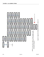
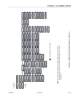
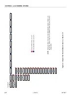
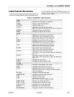
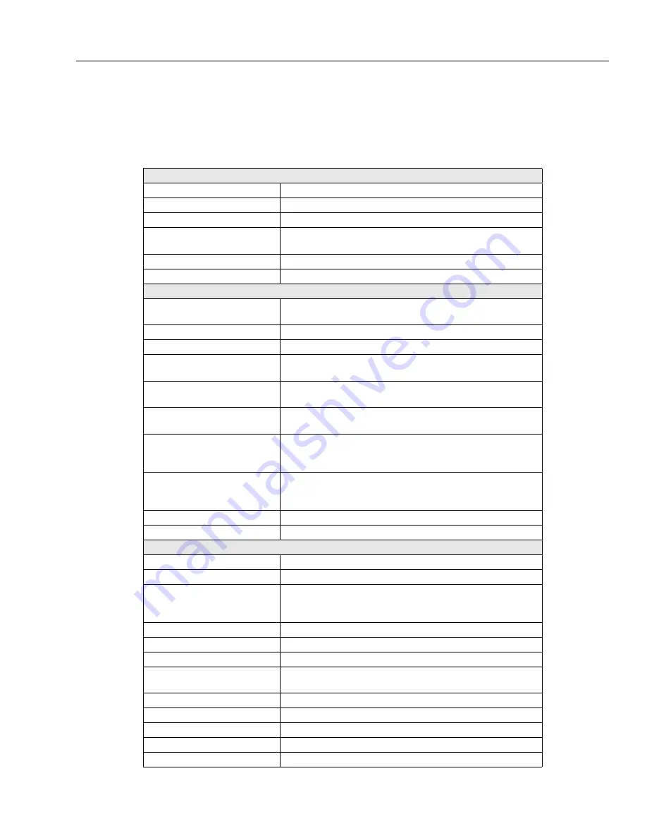
Analyzer Diagnostics Menu Structure
In the following structure descriptions, an intended item is
selected by pressing ENTER; pressing ESC steps back to
the next outer level. The LEFT/RIGHT arrow keys move
between items in the same level. The UP/DOWN arrow
keys alter a value if allowed
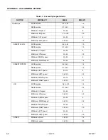
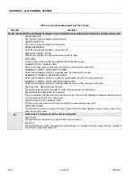
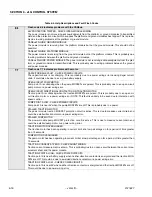
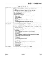
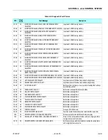
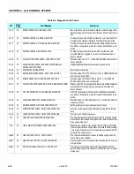
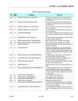
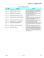
Table 6-5. DIAGNOSTICS - Menu Descriptions
DRIVE
DRIVE...
Displays drive joystick direction & demand
SPEED...
Displays vehicle direction & speed
POSITRAC...
Displays positrac status
STEER...
Displays steer switch direction & demand
NOTE: steer demand is inversely proportional to vehicle speed
BRAKES...
Displays brake control system status
CREEP...
Displays pump pot creep switch status
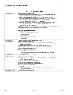
BOOM
LL....
Displays lower lift switch direction & demand
NOTE: demand is controlled by the pump pot
UL..
Displays upper lift joystick direction & demand
SWING...
Displays swing joystick direction & demand
LEVEL..
Displays basket level switch direction & demand
NOTE: demand is controlled by the pump pot
TELE...
Displays telescope switch direction & demand
NOTE: demand is controlled by the pump pot
ROTATE..
Displays basket rotate switch direction & demand
NOTE: demand is controlled by the pump pot
JIB (U/D).
Displays jib lift switch direction & demand
NOTE: demand is controlled by the pump pot Not displayed if
JIB = NO
JIB (L/R)
Displays jib swing switch direction & demand
NOTE: demand is controlled by the pump pot Not displayed if
JIB = NO
PUMP POT...
Displays pump pot demand
CREEP...
Displays pump pot creep switch status
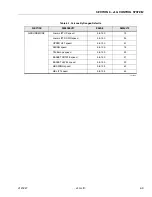
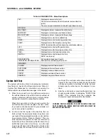
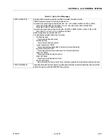
SYSTEM
TRACTION...
Displays measured traction motor current
PUMP...
Displays measured pump motor current
VALVE...
Displays measured valve (12V supply) current
NOTE: this includes current for the ground alarm & remoter,
but not for any lamps
BATTERY...
Displays measured battery voltage
TEMPERATURE...
Displays measured heat sink temperature
FSW1...
Displays footswitch status
FSW2...
Displays footswitch status
NOTE: FSW2 is wired to the platform module
DRIVE CUTOUT...
Displays drive cutout switch status
ELEV. CUTOUT...
Displays elevation cutout switch status
FUNC. CUTOUT...
Displays function cutout switch status
BRAKES...
Displays brake pressure switch status
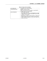
MAN.RELEASE...
Displays manual brake release switch status
Summary of Contents for JLG E400AJP
Page 2: ......
Page 32: ...SECTION 1 SPECIFICATIONS 1 18 JLG Lift 3121827 NOTES...
Page 42: ...SECTION 2 GENERAL 2 10 JLG Lift 3121827 NOTES...
Page 54: ...SECTION 3 CHASSIS TURNTABLE 3 12 JLG Lift 3121827 Figure 3 3 Speed Sensor Orientation...
Page 60: ...SECTION 3 CHASSIS TURNTABLE 3 18 JLG Lift 3121827 Figure 3 7 Steering Components and Spindles...
Page 62: ...SECTION 3 CHASSIS TURNTABLE 3 20 JLG Lift 3121827 Figure 3 9 Tilt Sensor Location...
Page 86: ...SECTION 3 CHASSIS TURNTABLE 3 44 JLG Lift 3121827 Figure 3 16 Swing Components...
Page 88: ...SECTION 3 CHASSIS TURNTABLE 3 46 JLG Lift 3121827 Figure 3 18 Battery Cable Connections...
Page 90: ...SECTION 3 CHASSIS TURNTABLE 3 48 JLG Lift 3121827 Figure 3 20 On Board Generator...
Page 97: ...SECTION 3 CHASSIS TURNTABLE 3121827 JLG Lift 3 55 Figure 3 22 Generator Components...
Page 116: ...SECTION 3 CHASSIS TURNTABLE 3 74 JLG Lift 3121827 NOTES...
Page 127: ...SECTION 4 BOOM PLATFORM 3121827 JLG Lift 4 11 Figure 4 10 Boom Limit Switches...
Page 140: ...SECTION 4 BOOM PLATFORM 4 24 JLG Lift 3121827 Figure 4 13 Rotator Counterbalance Valve...
Page 178: ...SECTION 5 HYDRAULICS 5 24 JLG Lift 3121827 Figure 5 26 HydraForce Cartridge Torque Value Chart...
Page 214: ...SECTION 6 JLG CONTROL SYSTEM 6 34 JLG Lift 3121827 NOTES...
Page 257: ......


