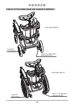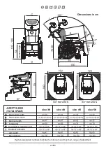
TECHNICAL FEATURES and MODELS
JUDITTA is available in 3 models:
•
JUDITTA B30 (tilt-in-space):
with 20 cm front solid swiveling wheels and 30
cm rear wheels; drum brakes are operated by a single control pedal.
•
JUDITTA B12 (tilt-in-space):
with four 12cm solid swiveling wheels, the rear
ones with brakes
•
JUDITTA B60 (tilt-in-space): with 20 cm. front solid wheels and 56 cm.
rear pneumatic wheels with hand brake and anti-tip device
-
FRAME
made of chromed steel, painted with non-tox
ic epoxy powder paint. Narrow
base to facilitate entering elevators
-
SEAT :
adjustable inclination from 10° to 35°; available in four widths (36, 40, 45 and
50 cm); inclined by 10° to prevent the user sliding forward.
-
HEADREST
wide and wrap-around, padded, height-adjustable, with vertical and front-
back rotation,
and lateral translation.
-
BACKREST
wide and retentive, can be adjusted in four positions to vary the depth of
the seat bottom
-
SEAT
low, to facilitate the user getting on and off
-
GAS SPRING
to adjust the inclination of the seat and backrest. The gas spring is a
mechanism that
supports the patient's weight during the adjustments
of the
backrest and of the seat tilting, with the following advantages: a) IT REDUCES THE
ASSISTANT'S EFFORT IN RAISING AND LOWERING SIGNIFICANTLY; b)
GUARANTEES UNIFORM MOVEMENT WITHOUT JERKING AND AVOIDS
UNBALANCING THE PATIENT DURING ADJUSTMENT; c) ALLOWS STOPPING
THE INCLINATION WHEREVER DESIRED
-
UPHOLSTERY
fireproof, breathable and removable for machine washing
-
SIDES
, closed, they can be opened to facilitate the user getting on and off
-
ARMRESTS
padded and height-adjustable
-
SIDE PROTECTIONS
padded for the knees
- FOOTRESTS
removable, and height-adjustable
- LEG SUPPORTS REMOVABLE,
tilt- and tilt adjustable. They can be turned sideways
to help the operator get close, the user get on and off. It is provided with padded
calfrests
19/86
Summary of Contents for Juditta B12
Page 2: ......
Page 12: ...10 86 ...
Page 27: ...ASSEMBLY BOTH SIDES 25 86 ...
Page 28: ...26 86 ...
Page 29: ...BOTH SIDES 27 86 ...
Page 30: ...CLAMPING LEVER INSERT THE HEADREST AND LOCK IT WITH THE CLAMPING LEVER 28 86 ...
Page 41: ...REMOVING THE LEGRESTS 1 PRESS THE LOCK BUTTON 2 REMOVE THE LEGREST Lock button 39 86 ...
Page 43: ...TURNING THE CALF RESTS 41 86 ...
Page 45: ...ADJUSTING THE HEIGHT OF THE ARMRESTS Locking lever FRONT VIEW Unlock Lock Locking lever 43 86 ...
Page 53: ...TILT ADJUSTMENT OF THE PUSH HANDLE BUTTON 51 86 ...
Page 61: ...ADJUSTING THE TILT OF THE TABLE VIEW FROM BELOW unlocked lever locked lever 59 86 ...
Page 63: ...ABDUCTION BLOCK 834 WARNING TIGHTEN THE KNOB WELL 61 86 ...
Page 65: ...B UNLOCKING the footrest lock LOCKING LEVER C OPERATING the footrest lock LOCKING LEVER 63 86 ...
Page 66: ...CALF REST 916 1 REMOVE THE KNEE PADS 64 86 ...
Page 67: ...2 FIX THE CALF REST 916 Adjust the depth by loosening the velcro 65 86 ...
Page 69: ...REMOVABLE TABLE COVER 896 VIEW FROM BELOW OF THE TABLE 67 86 ...
Page 71: ...IV POLE 933 B30 and B12 version 69 86 ...
Page 72: ...70 86 ...
Page 74: ...Strap Strap Strap 72 86 ...
Page 77: ...SET OF HAND BRAKES 905 B60 version Strap cable control doubler 75 86 ...
Page 78: ...Strap Strap Strap 76 86 ...
Page 79: ...77 86 ...
Page 80: ...cable lock cable cable control internal view 78 86 ...
Page 81: ...Hand brake lever sheath doupler B60 wheel with drum brake 79 86 ...
Page 89: ......
Page 90: ......
Page 91: ......

