


16
VCCX2 Controller Technical Guide
PART NO.
PART DESCRIPTION
ILLUSTRATION
PAGE NO.
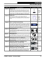
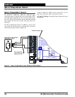
ASM01624
Strap-on Temperature Sensor Kit
Includes: Type III 10K ohm two-wire Strap-on Temperature Sensor, thermal
mastic, and plastic mounting strap. Used for water temperature sensing
applications.
Pages
43 and 44
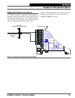
ASM01900 System Manager Touch Screen - Limited Access
The System Manager Touch Screen - Limited Access (SMTS-L) provides a
direct, graphic-enhanced, menu-driven link. The SMTS-L is an end-user interface
only and allows the end user to view status points, change Space Setpoints,
and view certain alarms of most controllers on the Orion Controls System. The
SMTS-L is equipped with a 4.3” 480 x 272 WQVGA RGB TFT LCD Touch Screen
Display. The System Manager TS-L is furnished with hardware for flush mounting
into hollow drywall or surface mounting on concrete brick or plaster surfaces.
Includes: SMTS-L with 12 ft. pigtail cable.
See the
System
Manager
TS-L
Technical
Guide
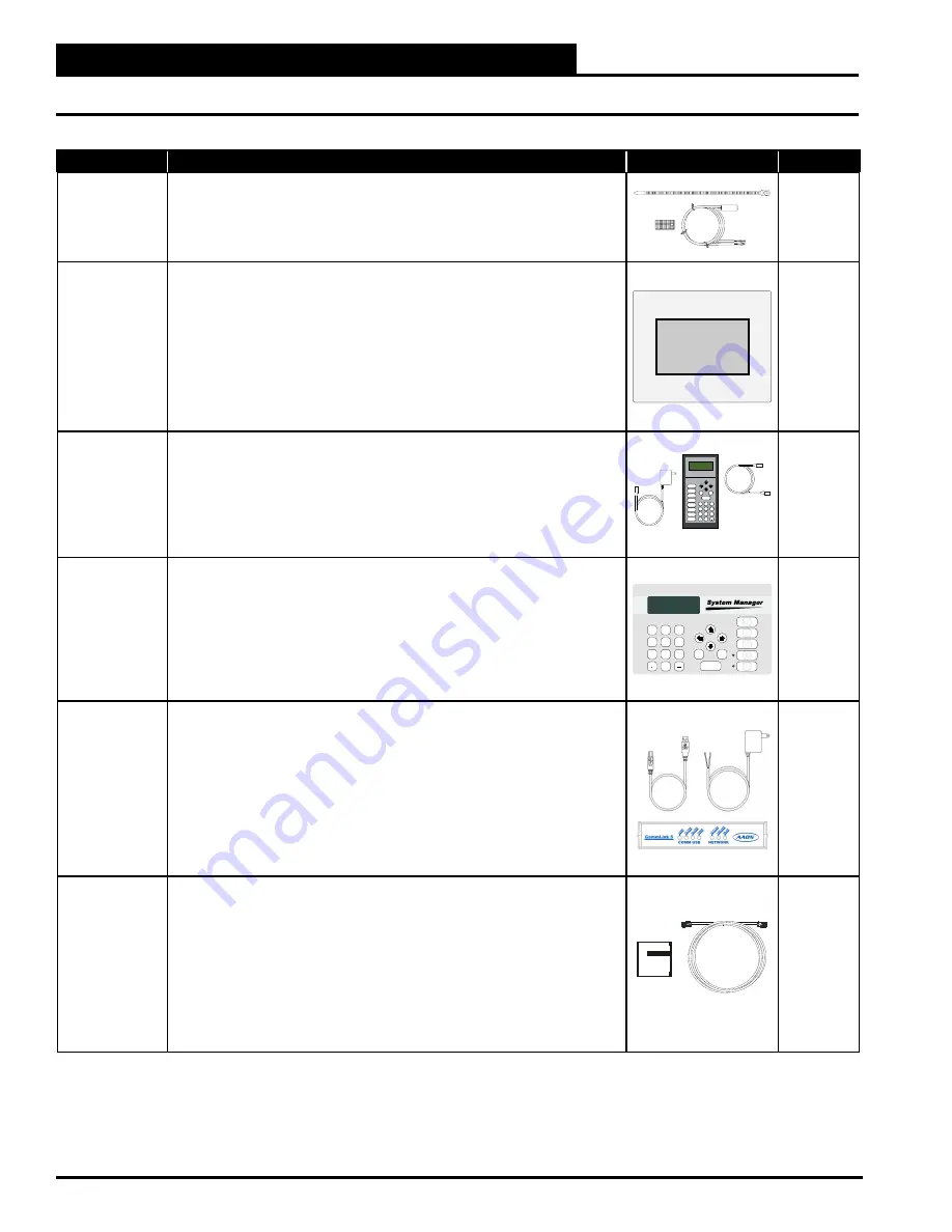
ASM01895
Modular Service Tool SD
Includes: Modular Service Tool, power supply, communication cables, 4 GB SD
card, and four AA batteries. Used to program and monitor all Orion controllers.
Mode
Selection
STATUS
SETPOINTS
SCHEDULES
OVERRIDES
ALARMS
CONFIGURATION
BALANCE - TEST
ON
7
8
0
DEC
MINUS
9
4
5
6
1
2
3
ENTER
ESC
CLLAR
DOWN
UP
PREV
NEXT
See the
VCCX2
Controller
Operator
Interfaces
SD
Technical
Guide
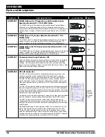
ASM01901
Modular System Manager SD
Includes: Modular System Manager SD with 4 GB SD card and 12 ft. pigtail
cable assembly. Used to program and monitor all Orion controllers. Designed for
hollow core wall mounting. When System Manager is to be mounted on a solid
wall (concrete), we recommend you attach the System Manager to a standard
handy box.
STATUS
SETPOINTS
SCHEDULES
OVERRIDES
ALARMS
7
8
0
DEC
MINUS
9
4
5
6
1
2
3
ENTER
ESC
CLLAR
DOWN
UP
PREV
NEXT
See the
VCCX2
Controller
Operator
Interfaces
SD
Technical
Guide
ASM01874
CommLink 5 Communications Interface
The CommLink 5 connects to your control system using a USB computer
connection to provide direct on-site communications with the control system from
a computer with the Prism 2 software installed. For remote communications, see
the IP Module Kit.
Includes: CommLink 5, 6 ft. USB cable, and 120/24 VAC power supply. Required
on all networked systems or if direct computer or remote computer connection
is required. Connects to your computer’s USB 1.1 or 2.1 port. Prism 2 computer
front-end software must be installed on the direct connected or remote
connected computer in order to communicate with your system.
See the
CommLink
5 Technical
Guide
ASM01902
IP Module Kit - Internet/LAN Connection
Used for Internet or Local Area Network communications with the control system.
Field installs by plugging into the CommLink 5 circuit board and provides an
addressable Ethernet connection to the controls system from any computer
connected to your building’s LAN. It can also be configured to allow access to
the control system from the Internet through your LAN if your Ethernet firewall is
configured for this option.
Includes: IP Link module, 10 ft. long Ethernet cable, and installation instructions.
Prism 2 computer front-end software must be installed on the remote computer
in order to dial-up and communicate with the controls system.
See the
IP Module
Technical
Guide
OVERVIEW
Parts and Descriptions


