10
z
Noise suppression parts (accessories)
Refer to p.12 for accessories.
•
Connection cable (for signal)
This cable is a shielded twisted pair cable for good noise immunity to connect
the driver and controller. The ground wires useful to grounding are provided
at both ends of the cable. The EMC measures are conducted using the
Oriental Motor connection cable.
•
Pulse signal converter for noise immunity
This is a noise filter for pulse signal lines. It eliminates the noise of the pulse
signal, and converts the pulse signal to the line driver type.
•
Surge suppressor
This product is effective to suppress the surge which occurs in a relay contact
part. Connect it when using a relay or electromagnetic switch. CR circuit for
surge suppression and CR circuit module are provided.
Conformity to the EMC Directive
Effective measures must be taken against the EMI that the motor and driver
may give to adjacent control-system equipment, as well as the EMS of the
motor and driver itself, in order to prevent a serious functional impediment in
the machinery. The use of the following installation and wiring methods will
enable the motor and driver to be compliant with the EMC directive. Refer to
p.2 for the applicable standards.
Oriental Motor conducts EMC measurements on its motors and drivers in
accordance with the following "Example of motor and driver installation and
wiring."
The user is responsible for ensuring the machine's compliance with the EMC
Directive, based on the installation and wiring explained below.
•
Power supply
The
CVK
Series is a product of DC power input. Use a DC power supply
(switched-mode power supply etc.) that conforms to the EMC Directive.
•
Connecting the signal cable
Refer to "Prevention of noise propagation" on p.9.
•
How to ground
y
The cable used to ground the motor and driver must be as thick and short
as possible so that no potential difference is generated.
y
Choose a large, thick and uniformly conductive surface for the grounding
point.
y
Install the motor to the grounded metal plate.
•
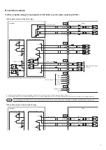
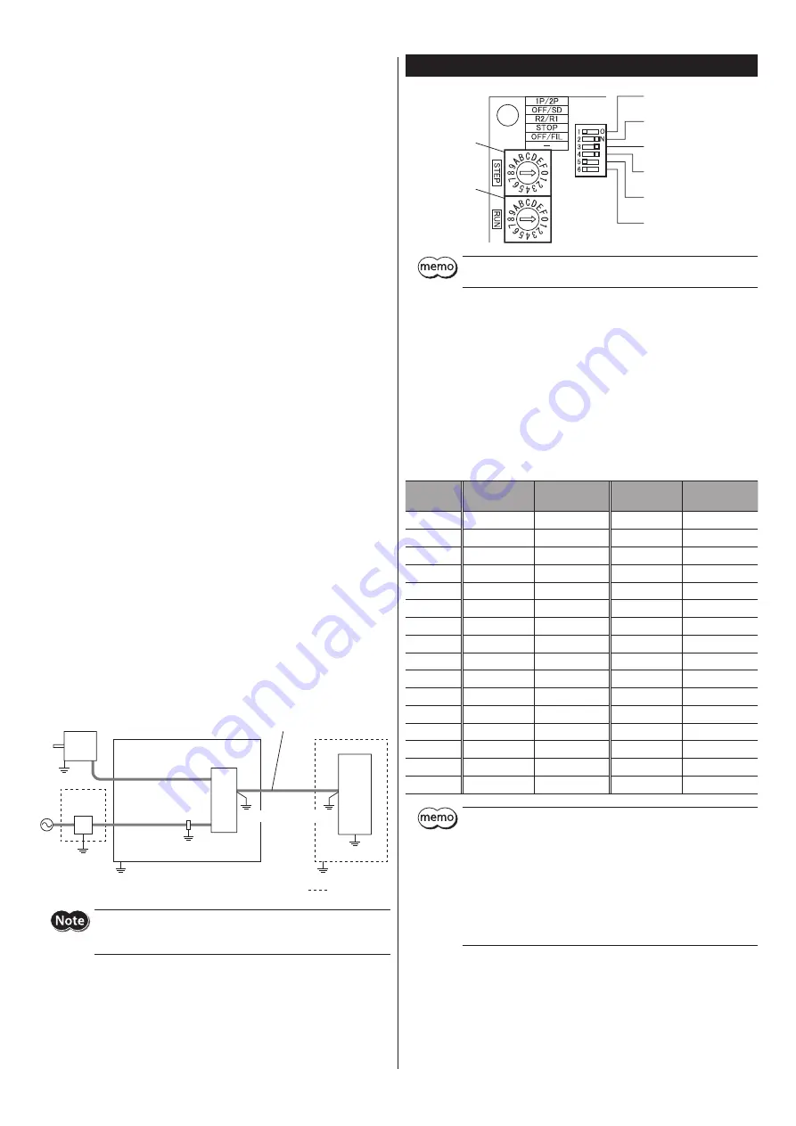
Example of motor and driver installation and wiring
Motor
Driver
DC power
supply
Cable
clamp
Grounded panel
Motor cable
Controller
Power supply
cable
Signal cable
(connection cable)
Grounding
is a shield box.
Grounding
Grounding
Grounding
Grounding
Grounding
Grounding
Grounding
The driver uses parts that are sensitive to electrostatic charge. Take
measures against static electricity since static electricity may cause
the driver to malfunction or suffer damage.
Setting
No.5: OFF/FIL switch
(command filter)
No.6: Not used.
STEP switch
(step angle)
No.1: 1P/2P switch
(pulse input mode)
No.2: OFF/SD switch
(smooth drive function)
No.3: R2/R1 switch
(resolution)
No.4: STOP switch
(standstill current rate)
RUN switch
(operating
current rate)
The STEP switch, 1P/2P switch, and R2/R1 switch are enabled after the
power is cycled.
Step angle
Set the motor step angle using the R2/R1 switch and STEP switch. See the
following tables for the step angles that can be set.
Factory setting
R2/R1 switch: ON side (R1) for 5-phase stepping motor
OFF side (R2) for 2-phase stepping motor
STEP switch: 0
•
When the R2/R1 switch
is set to ON side (R1).
•
When the R2/R1 switch
is set to OFF side (R2).
STEP switch
Resolution
(P/R)
Step angle
Resolution
(P/R)
Step angle
0
500
0.72°
200
1.8°
1
1000
0.36°
400
0.9°
2
1250
0.288°
800
0.45°
3
2000
0.18°
1000
0.36°
4
2500
0.144°
1600
0.225°
5
4000
0.09°
2000
0.18°
6
5000
0.072°
3200
0.1125°
7
10000
0.036°
5000
0.072°
8
12500
0.0288°
6400
0.05625°
9
20000
0.018°
10000
0.036°
A
25000
0.0144°
12800
0.028125°
B
40000
0.009°
20000
0.018°
C
50000
0.0072°
25000
0.0144°
D
62500
0.00576°
25600
0.0140625°
E
100,000
0.0036°
50000
0.0072°
F
125,000
0.00288°
51200
0.00703125°
y
Step angles are theoretical values.
y
Do not change the CS input or switches while operating. Doing so
may cause loss of synchronism of the motor, resulting in the motor
standstill.
y
For the high-resolution type, in comparison with the standard type
the resolution is twice and the step angle is one-half.
Example: When the R2/R1 switch is set to the ON side (R1) and the
STEP switch is set to "0"
Resolution of the high-resolution type: 500 × 2 = 1000
Step angle of the high-resolution type: 0.72°/2 = 0.36°
Pulse input mode
Set a desired pulse input mode of the driver according to the pulse output
mode of the controller used with the driver. Set a desired mode using the
1P/2P switch. The factory setting of the pulse input mode depends on the
destination country.

