7
Motor
model
Gear
ratio
Permissible radial load [N (lb.)]
Permissible
axial load
[N (lb.)]
Distance from the tip of motor output shaft
[mm (in.)]
0
(0)
5
(0.2)
10
(0.39)
15
(0.59)
20
(0.79)
ARM66
5
240
(54)
260
(58)
280
(63)
300
(67)
330
(74)
200 (45)
7.2
270
(60)
290
(65)
310
(69)
340
(76)
370
(83)
10
300
(67)
320
(72)
350
(78)
380
(85)
410
(92)
25
410
(92)
440
(99)
470
(105)
520
(117)
560
(126)
36
360
(81)
410
(92)
480
(108)
570
(128)
640
(144)
50
360
(81)
410
(92)
480
(108)
570
(128)
700
(157)
ARM98
5
370
(83)
390
(87)
410
(92)
430
(96)
460
(103)
600 (135)
7.2
410
(92)
440
(99)
460
(103)
490
(110)
520
(117)
10
460
(103)
490
(110)
520
(117)
550
(123)
580
(130)
25
630
(141)
660
(148)
700
(157)
740
(166)
790
(177)
36
710
(159)
750
(168)
790
(177)
840
(189)
900
(200)
50
790
(177)
840
(189)
890
(200)
940
(210)
1,000
(220)
•
Harmonic geared type
Motor model
Permissible radial load [N (lb.)]
Permissible axial
load [N (lb.)]
Distance from the tip of motor output shaft
[mm (in.)]
0
(0)
5
(0.2)
10
(0.39)
15
(0.59)
20
(0.79)
ARM24
100
(22)
135
(30)
175
(39)
250
(56)
−
140 (31)
ARM46
180
(40)
220
(49)
270
(60)
360
(81)
510
(114)
220 (49)
ARM66
320
(72)
370
(83)
440
(99)
550
(123)
720
(162)
450 (101)
ARM98
1,090
(240)
1,150
(250)
1,230
(270)
1,310
(290)
1,410
(310)
1,300 (290)
z
Permissible moment load of the Harmonic geared type
Motor model
Gear ratio
Permissible moment load (N·m)
ARM24
All gear ratios
2.9
ARM46
5.6
ARM66
11.6
•
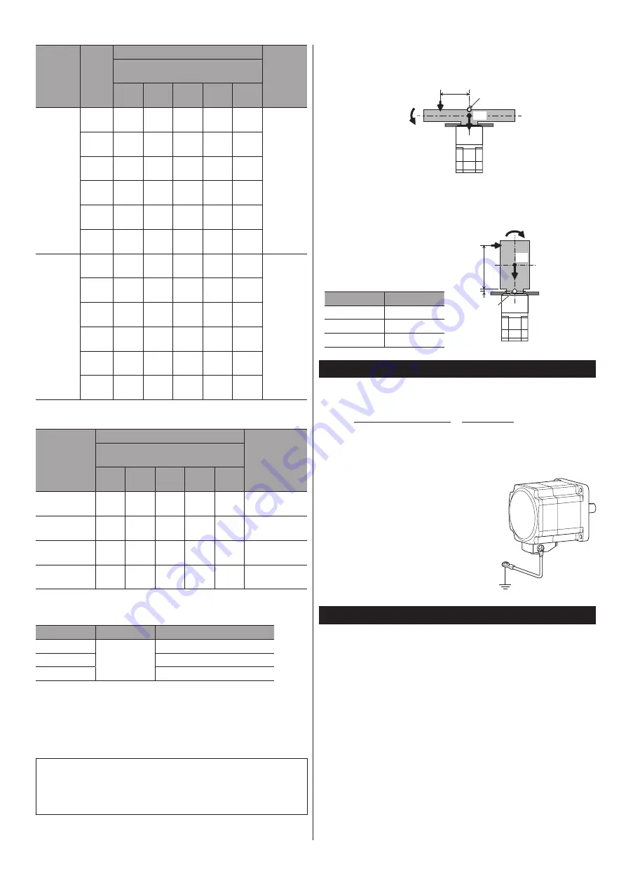
Calculation of moment load
If an eccentric load is applied on the flange surface when installing an arm or
a table, calculate the moment load using the formula next. The moment load
should not exceed the permissible value.
How to read a code
y
m: Mass of a load (kg)
y
g: Gravitational acceleration (m/s
2
)
y
F: External force (N)
y
L: Overhang distance (m)
y
a: Constant (m)
y
ΔF: Load applied on the output
flange surface (N)
y
Fs: Permissible axial load (N)
y
ΔM: Load moment (N·m)
y
M: Permissible moment load (N·m)
Example 1; When an external force F(N) is applied on a position
overhanging by L (m) from the center of the output
flange in the horizontal direction
y
Load moment
ΔM = F • L
ΔM ≤ M
y
Axial load
ΔF = F + m • g
ΔF ≤ Fs
L
F
ΔM
Fulcrum point
mg
Example 2; When an external force F(N) is applied on a position
overhanging by L (m) from the output flange mounting
surface in the vertical direction
y
Load moment
ΔM = F • (L + a)
ΔM ≤ M
y
Axial load
ΔF = m • g
ΔF ≤ Fs
Fulcrum point
mg
ΔM
F
L
a
Motor model
Coefficient “a”
ARM24
0.0073
ARM46
0.009
ARM66
0.0114
Connection
Connecting to the driver
Refer to OPERATING MANUAL Driver or USER MANUAL for the connection
method. If connector covers are attached on cables, cover the connected
connectors using them.
Grounding the motor
Be sure to ground the Protective Earth Terminal
of the motor. (Not required when the driver's
power supply specification is 24 VDC.)
Screw size: M4
Tightening torque: 1.2 N·m (170 oz-in)
Use a grounding wire larger than AWG18
(0.75 mm
2
).
Use a round terminal when grounding, and
secure it with a mounting screw with a washer.
Ground wires and crimp terminals are not
included.
Grounding
Inspection and maintenance
Inspection
It is recommended that periodic inspections be conducted for the items listed
below after each operation of the motor. If an abnormal condition is noted,
discontinue any use and contact your nearest Oriental Motor sales office.
•
During inspection
y
Are any of the screws having installed the motor loose?
y
Check for any unusual noises in the motor bearings (ball bearings) or other
moving parts.
y
Are the motor output shaft and load shaft out of alignment?
y
Are there any scratches, signs of stress or loose driver connections in the
motor cable?
Warranty
Check on the Oriental Motor Website or General Catalog for the product
warranty.


