134
SPARC M5-32 and SPARC M6-32 Servers Installation Guide • December 2014
▼
Connect the EMS Network Cables
Each EMS contains two 10-GbE RJ-45 ports (10GBASE-T) that provide the network
connection to the server.
Depending on your configuration, connect at least one Category 6A or 7 network
cable to an EMS port on each PDomain. To provide redundancy, connect the two
network cables from an EMS from one PDomain to two separate network switches or
hubs on your network.
Note –
To achieve 10-GbE network speeds, you must use Category 6A or Category 7
network cables, and your network switches or hubs must support the 10GBASE-T
Ethernet standard. The network cable length must not exceed 328 ft (100 meters).
Caution –
Only EMS modules are supported in the EMS slots. Installing other PCIe
express modules in these slots is not supported and could damage the server and the
express module.
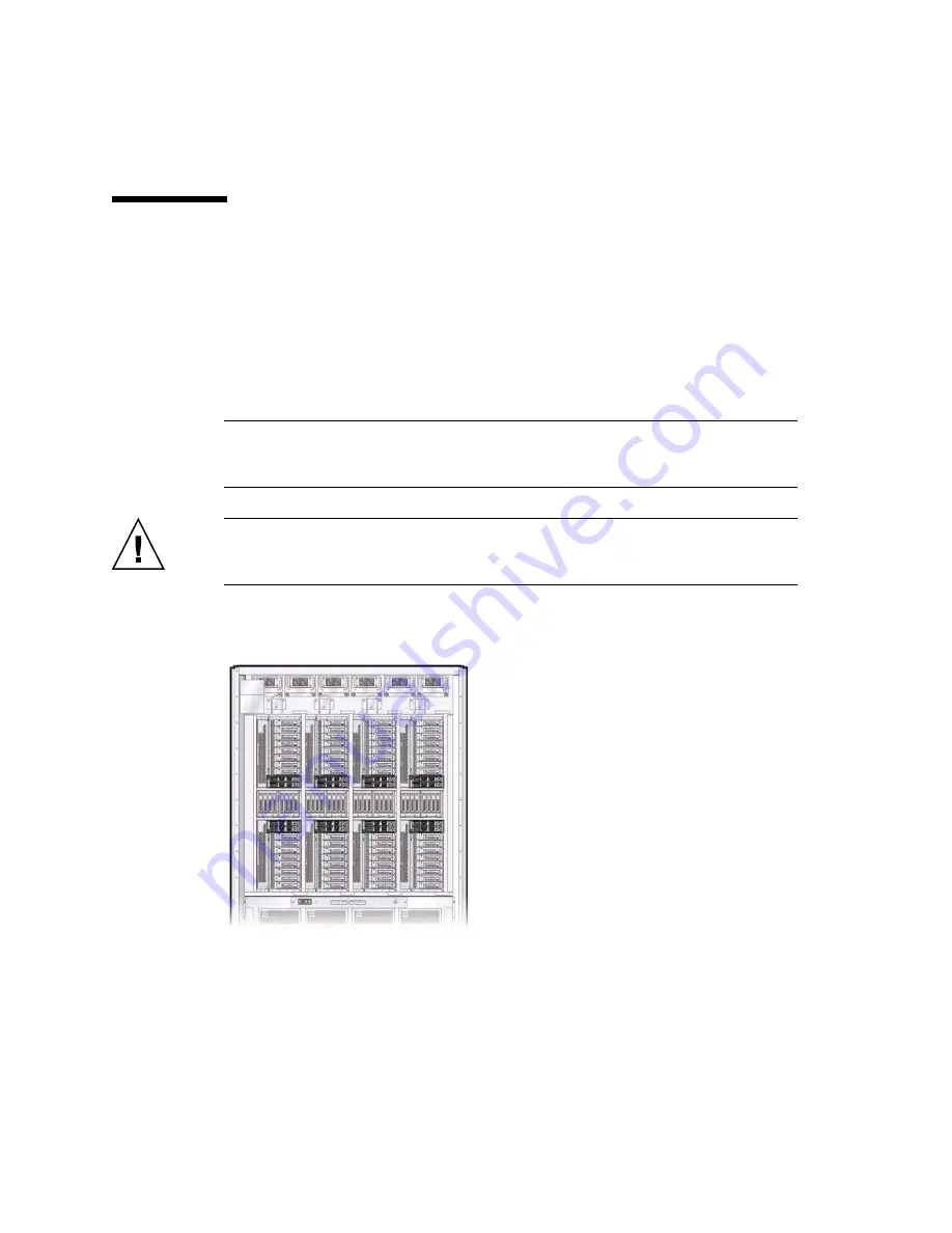
1. Locate the EMS modules at the rear of the server.
The EMS modules are located in each IOU, above and below the hard drives.
2. Connect a Category 6A (or better) cable from your network switch or hub to the
10-GbE port 0 on the EMS.
Summary of Contents for sparc M5-32
Page 1: ...SPARC M5 32 and SPARC M6 32 Servers Installation Guide Part No E41215 05 December 2014 ...
Page 8: ...viii SPARC M5 32 and SPARC M6 32 Servers Installation Guide December 2014 ...
Page 16: ...6 SPARC M5 32 and SPARC M6 32 Servers Installation Guide December 2014 Front Components ...
Page 18: ...8 SPARC M5 32 and SPARC M6 32 Servers Installation Guide December 2014 Rear Components ...
Page 21: ...Understanding the Server 11 FIGURE DCU Locations Rear of Server ...
Page 51: ...Preparing the Site 41 ...
Page 82: ...72 SPARC M5 32 and SPARC M6 32 Servers Installation Guide December 2014 ...
Page 106: ...96 SPARC M5 32 and SPARC M6 32 Servers Installation Guide December 2014 ...
Page 182: ...172 SPARC M5 32 and SPARC M6 32 Servers Installation Guide December 2014 ...


