DA-4PM/0 version 1.0.E
5
Mainframe for
4 modular amplifiers
DA-4PM/0
3.
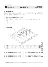
DA-4PM/0 REAR VIEW
1)
DA-4PM/0 Ground terminal.
2)
15A Mains fuse for 220-240 VCA. The device is set
up with a 15A fuse to operate on a main voltage of
220-240 VAC. To work with other main voltages
(100-127 VAC), replace the 15A fuse with the 30A
fuse supplied with the device.
ATTENTION: MAKE SURE TO DISCONNECT THE
POWER CORD FROM THE AC INLET BEFORE
REPLACING A FUSE.
3)
100-240V AC 50/60 Hz AC Inlet connector.
4)
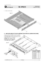
Slot 4 / amplifier 4 controls and connections.
5)
Slot 3 / amplifier 3 controls and connections.
6)
Slot 2 / amplifier 2 controls and connections.
7)
Slot 1 / amplifier 1 controls and connections.
8)
Amplifier
DC Fuse
receptacle (see section 6). ONLY for
MP-WDC amplifiers series with secondary 24 VDC power
supply.
9)
Amplifier
LINE OUTPUT SPEAKERS
connection (see
section 4.1).
10)
STANDBY
Control. Link these two contacts to activate
standby mode (see section 4.3).
11)
Amplifier
INPUT
RJ45 connector (see section 4.2).
12)
STANDBY
LED indicator. Yellow LED.
The LED lights up when the STANDBY MODE is activated
through the standby control contact of the rear power
strip.
The LED lights blinking when the amplifier hot swapping
screw is not fixed to the mainframe, so the amplifier is in
standby mode.
13)
PRIORITY
LED indicator. Green LED. Lights when priority
contact (see section 4.2) is activated by an external
device.
14)
Amplifier
VOLUME
adjustment.
15)
24V DC
Main connector (see section 4.4). ONLY for MP-
WDC amplifiers series with secondary 24 VDC power
supply.
4.
CONNECTION
4.1.
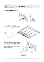
Speakers connection
The equipment has four channels (one
per amplifier) for the connection of
100V high impedance speaker lines.
Figure 2
WARNING:
The sum of the power ratings of the loudspeakers
connected to the output of an amplifier must not exceed
the power of the amplifier module.
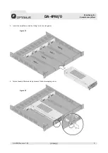
Figure 3


