Optronis CP70-004-M/C-19000 User Manual Download Page 34


-34- 

7


Firmware Update 

Camera  firmware  update  is  available  through  camera  Aux  connector  by  using  the  camera  accessory 

“P

rogramming cable

”. This cable allows an USB connection to a PC

 and must be used together with Optronis 

Windows 

update software “UCXP_flash.exe”.


Before updating camera firmware, please check product website page (download tab) to 
be sure that you have: 


The Last Firmware Version 


The Last Firmware Update Software Version (Setup_UCXP_Flash_vx.y.z.exe) 


Update 

process is described in “ReadMe.pdf” file generated when installing UCXP Flash.exe. Please check this 

file to get the last up to date firmware update process description. Default folder is: 

C:\Program Files (x86)\Optronis\UCXP_Flash_vx.x.x\Documentation\  

Please find below a quick description of the updating process: 

1)


If your software is out of date or if this is the first use: 

Execute  last  version  of  “Setup_UCXP_Flash_v

x.y.z

.exe”  to  install 

Firmware  Update  Software  and 

Programming cable Drivers. 
Restart computer. 

2)


Connect USB cable to PC and camera Aux input. 
Use PC rear USB ports as front ports are often not working. 

3)


Power cycle the camera. 

4)


Start UCXP_Flash.exe 

5)


Select your camera series 


Figure 16: Camera Series Selection 
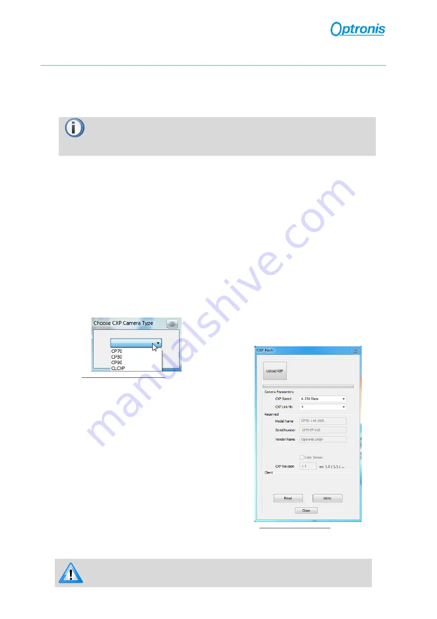
 

6)


When UCXP_flash.exe is connected to the 
camera, camera LEDs become solid RED. 

Click on “Upload R

B

F” button and select the 

new firmware (.rbf file) 


Figure 17: Software Interface 

7)


Wait end of process (10 to 20 minutes, depending on camera and firmware size) 
Power cycle camera when programming is finished. 


If remaining time is higher than 20min, it often means that the cable is not well 

detected. Close software and end “UCXP_flash” process if

 it is still running. 

Choose another USB port, power cycle camera and restart software. 

Summary of Contents for CP70-004-M/C-19000

Page 1: ...Optronis CoaXPress Cameras CamPerform CP70 Series User Manual CP70 004 M C 19000 Document Reference 1876 SU 01 E Release Date 17 08 2018...

Page 2: ...ve any further questions or if you wish to claim a service or warranty case please contact your local dealer or refer to the Optronis support You can contact our support by using our website or by ema...

Page 3: ...11 3 1 Model Description 11 3 1 1 Model Name and Options 11 3 2 Technical Data 12 3 2 1 General Info 12 3 2 2 Spectral Response 13 3 2 3 Glass Filter 14 3 2 4 Mechanical Drawings Dimensions and Mount...

Page 4: ...liary Connector 26 5 1 5 CoaXPress Status LEDs 28 6 Camera Control Interface 29 6 1 GenICam XML Interface 29 6 1 1 CoaXPress GenICam Compliant Interface 29 6 1 2 XML Entry Access Mode 29 6 1 3 XML Ent...

Page 5: ...13 Figure 7 Glass Filter typical transmittance 1830 SS 10 IR Filter 14 Figure 8 CP70 Dimensions with F Mount option 15 Figure 9 Camera Single ROI control 17 Figure 10 Sync Timings 20 Figure 11 CP70 H...

Page 6: ...6 1 General 1 1 Declaration of Conformity...

Page 7: ...rks The following signs are used in this user manual to highlight some information Remarks and additional information Attention warnings 1 5 Scope of Delivery The camera is delivered together with Bri...

Page 8: ...e power over Coaxpress PoCXP or delivered external power supply option Temperature and Humidity Please respect recommended conditions You may use controlled airflow or heatsinks to keep camera in bett...

Page 9: ...ling or removing camera lens Depending on your lens mount type and lens pay attention to following points If your lens has a mounting mark first align lens holder and lens mounting marks and then rota...

Page 10: ...ng formula distances in millimeters Alternatively if you already have a lens you can compute working distance using the following formula distances in millimeters Examples PixelSize 0 008mm Full resol...

Page 11: ...s CamPerform camera series decoding information are illustrated here after Check camera label on the bottom side to get both Ref Camera Model Name see Figure 3 S N Camera Serial Number see Figure 4 Fi...

Page 12: ...FWC 17000 e SNR 45 dB DSNU1288 57 5 e PRNU1288 1 27 Non linearity error 0 5 calibrated 0 2 Shutter efficiency global electronic shutter Trigger signal TTL 3 3 5 V 10 mA optically isolated Trigger mod...

Page 13: ...13 3 2 2 Spectral Response Figure 5 Camera Spectral Response monochrome Figure 6 Camera Spectral Response color...

Page 14: ...lter Color cameras CP70 1 C 1000 model are delivered with an IR filter placed in front of the sensor Its typical transmittance is illustrated on Figure 7 Figure 7 Glass Filter typical transmittance 18...

Page 15: ...15 3 2 4 Mechanical Drawings Dimensions and Mounting Points CP70 Mechanical Dimensions with F Mount FM option Figure 8 CP70 Dimensions with F Mount option...

Page 16: ...raph Please check also 6 2 XML Main Entries Features Description page 31 paragraph to have a precise description of allowed values for each entry 4 1 Frame Format 4 1 1 Supported Pixel Formats The cam...

Page 17: ...17 Figure 9 Camera Single ROI control...

Page 18: ...an external signal to generate frames You must apply a TTL signal the Sync In input of the camera Please respect signal limits current and voltage and use the Aux to BNC adapter or respect Aux connec...

Page 19: ...lect the control source o Granularity On Same as in the Continuous mode camera register controls the exposure and can be modified using camera XML control interface o Granularity Off The exposure is c...

Page 20: ...ularity is disabled Off o T2 is controlled by user external generator signal period o T1 is controlled by user external generator pulse width In both cases timings must be respected Synchronization ov...

Page 21: ...this formula _ _ _ 4 5 Sync Out Output The camera output Sync Out delivers a TTL signal reflecting camera frame acquisition External synchronization may be operated in level detection mode Please see...

Page 22: ...unter incrementing with every frame transferred 24 next bits contain a micro second precision counter that indicates the time when the frame exposure has started When disabled No no information is int...

Page 23: ...cond command SaveToFlashWithRebootAndWithAutoStart save user configuration but also force live acquisition start without requiring any frame grabber command Beware that if frame grabber sends Connecti...

Page 24: ...1 2 Powering Camera Camera can be powered either by Power over Coaxpress PoCXP or using its external power connector Using PoCXP When using PoCXP the power is supplied by the Frame Grabber through CXP...

Page 25: ...our power supply must respect bellow characteristics CP70 Series Connector info Camera P connector type Hirose HR10A 7R 4S Cable Connector Hirose HR10A 7P 4P Connector View Figure 12 CP70 Power Connec...

Page 26: ...s Camera accessory Programming cable allows an USB connection to a PC for firmware updates CP70 Series Connector info Camera A connector type Hirose HR10A 7R 6S Cable Connector Hirose HR10A 7P 6P Conn...

Page 27: ...r is negligible 0mA Easiest driver circuit is a transistor working in open collector configuration Figure 14 Sync In Input Schematics Sync Out Sync Out has a built in 50 Ohm driver The output principl...

Page 28: ...wer Off System booting Solid orange or Led Chaser Powered but nothing connected only for power over power connector Slow pulse red Link detection in progress PoCXP active Fast flash green Link detecti...

Page 29: ...spond to a camera feature and use its own access type values ranges etc Paragraphs here after are explaining more in details how to use this XML file 6 1 2 XML Entry Access Mode Each XML entry have a...

Page 30: ...ters LSB and MSB to identify the right bits Example If an XML entry has Mask LSB 31 MSB 16 it means that the you access a 4bytes 32bit register and only the upper 16 bits are used by this entry 6 1 6...

Page 31: ...imation or any other function changing the horizontal dimension of the image HeightMax 0x6004 RO Integer Mask LSB 15 MSB 0 Maximum height in pixels of the image This dimension is calculated after vert...

Page 32: ...e rate in Hz ExposureTime 0x60C8 RW Float Min 2 Max dynamic depends on other parameters Max available at address 0x60CC Sets the Exposure time in microseconds when ExposureMode is Timed This controls...

Page 33: ...RW Enumeration List On Off Mask LSB 8 MSB 15 Switch ON OFF indicator lamps AddCounterInformation 0x6160 RW Enumeration List Yes no AddCounterInformation Gain 0x6144 RW Enumeration List x1 x2 x4 Analog...

Page 34: ...f the updating process 1 If your software is out of date or if this is the first use Execute last version of Setup_UCXP_Flash_vx y z exe to install Firmware Update Software and Programming cable Drive...

Page 35: ...ent New presentation and layout Synchronized content with datasheet v08 2017 8 2 Firmware Revision Firmware Revision Date Description v13 0 5 24 04 2018 Minor corrections Improve stability when modify...

Reviews: