-
64
-
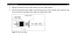
1. For a dismantling on the head side open the cover plate on the back side of the head first. Then
remove the terminal block and loose the connections.
2. After the new cable has been installed proceed in reversed order. Be careful the cable shield is
properly connected to the head housing.
4.7 Outputs and Inputs
4.7.1
Analog outputs
The CTlaser has two analog output channels.
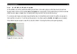
Consider that there are different connection pins on the mainboard (
OUT-mV/mA
or
OUT-TC
)
according to the chosen output signal.
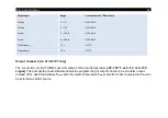
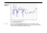
Output channel 1
This output is used for the object temperature. The selection of the output signal can be done via the
programming keys
. The CompactConnect software allows the programming of output
channel 1 as an alarm output.
Summary of Contents for CTlaser 05M
Page 1: ...Operator s Manual optris CTlaser LT LTF 05M 1M 2M 3M MT F2 F6 G5 P7 Infrared thermometer...
Page 8: ...8 Appendix C Smart Averaging 96 Appendix D Declaration of Conformity 97...
Page 44: ...44 Figure 2 Mounting bracket adjustable in one axis Order No ACCTLFB standard scope of supply...
Page 45: ...Mechanical Installation 45 Figure 3 Electronic box...
Page 97: ...Appendix D Declaration of Conformity 97 Appendix D Declaration of Conformity...
Page 98: ...optris CTlaser E2018 12 A...


