CHAPTER 1: INSTALLATION AND TESTING
SNAP High-Density Digital Module User’s Guide
7
Attaching the Cable
Cables (wiring harness assemblies) are sold separately. See the compatibility chart in
to determine the cable you need. If you are making your own cables, see
1.
Plug the cable into the wiring connector(s) on the top of the module.
2.
Secure the harness cable so that its weight is supported. The connector plug is not designed to support
the weight of the cable.
Setting Up the Breakout Board
For ease in wiring the module to field devices, we recommend you use a breakout board or install a barrier
strip in a convenient location.
Wiring varies based on the module, cable, and breakout board combination. See the wiring diagrams and
instructions in form 1756,
SNAP TEX Cables and Breakout Boards Data Sheet.
TESTING FIELD CONNECTIONS
Once you have the module wired, we recommend testing field wiring locally using the OptoTerminal-G20
(sold separately). For input and output modules, you can use the terminal to read point states; for output
modules, you can also use it to write to individual output points.
CAUTION: The OptoTerminal-G20 is for use with SNAP high-density modules only, and is the only display device
intended for use with these modules. Any use of the display device on other equipment, or the use of another display
device with a high-density digital module, may damage your equipment.
Reading Point States
1.
Turn on power to the rack.
2.
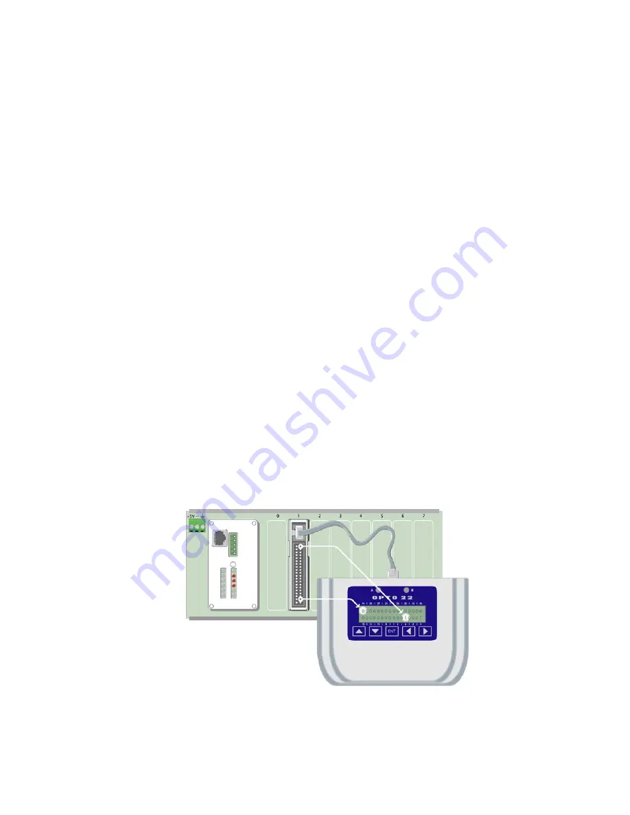
Use the correct cable to connect the OptoTerminal-G20 to the RJ-45 connector on a 32-channel module
or the 6-pin connector on a 16-channel module (match up the keying dots).
As shown in the diagram below, the OptoTerminal-G20 displays the current state of all points on the
module.
Point states are displayed as a bitmask. Each binary digit represents the state of one point, either on (1) or
off (o). The top row shows points 31–16 and the bottom row shows points 15–0.
Wiring harness not shown


