background image

User Manual – ePX 200


OptiPro Systems, LLC. 

Page 43 of 60 

Last Modified: 7/30/2014 

8.2


Z-Axis Over Travel at Cycle End 

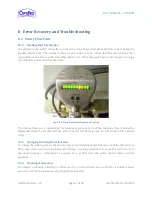
This error will occur when the Z axis load offset is too large. The machine is effectively trying to move Z 
beyond the axis limits.  The machine will not physically move the axis but will fault before moving the 
axis based on the calculations it is performing.  To clear the fault, press ok to acknowledge the message, 
press 

RESET

, wait for the red screen to change to blue, and turn 

SERVOS

 on. You will need to change the 

Z axis load offset to the correct maximum value.  First, scroll down the code in the auto screen (which 
should still be up) until the line with the command  [G54] is in view, and note the Z value underneath. 
Press 

MANUAL  MODE

;  the  machine  will  still  be  in  [G54]. Press  Z+  until  the  Z axis  stops  in  its  bottom 

most position. Note this second  Z value. Subtract  the original value from the second value,  giving you 
the maximum Z value for the load offset. This value will vary based on the individual tool set, because it 
is based partially on tool geometry (tool length, reception height etc.). To set the new Z axis load offset 
tap [Settings], enter the new value into the field labeled [Z Axis Load Offset] and tap save at the bottom 
of the screen. 

8.3


Recovering from Error Messages 

A slurry flow fault, low air pressure, unreferenced axes or Z Axis over travel may cause error messages to 
appear  on  the  user  interface.    To  clear  these  messages  and  re-gain  your  control  of  the  machine,  the 

RESET

  button  must  be  pressed  after  action  to  correct  the  error  has  been  taken,  to  clear  messages. 

Contact OptiPro Service if additional support is needed. 

For example:  If you see a low air pressure error message, it may be because your air compressor was 
shut  off  at  some  point  causing  the  machine  to  fault  out.    If  your  compressor  has  already  been  turned 
back  on,  the  only  step  needed  to  clear  the  error  is  to  hit  the 

RESET

  button.    If  the  software  has  been 

closed, the axes are no longer referenced.  This will cause an error message to appear.  Press the 

RESET


button, turn the 

SERVOS

  on, then 

ZERO

  and then 

CYCLE  START

.  This will reference the axes and your 

machine will be ready for production. 

Table 8-1: Fault Messages 

FAULT MESSAGE 

M  10 

GREASE LUBE LONG CYCLE FAULT 

M  11 

GREASE LUBE PRESSURE SW. STUCK-ON FAULT 

M  12 

GREASE LUBE LOW LEVEL FAULT 

M  13 

GREASE LUBE CONSECUTIVE LONG CYCLE FAULT 

M  15 

SERVO POWER SUPPLY FAULT 

M  17 

S2/C-AXIS DRIVE FAULT 

M  19 

S1 POLISHER SPINDLE DRIVE FAULT 

M  20 

LOW SYSTEM AIR PRESSURE FAULT 

M  24 

VACUUM PUMP RUN FAULT 

M  30 

S2/C-AXIS WORK SPINDLE AIR PURGE FAULT 

M  31 

S1 POLISHER SPINDLE AIR PURGE FAULT 

Summary of Contents for ePx 200

Page 1: ...User Manual ePX 200 OptiPro Systems LLC Page 1 of 60 Last Modified 7 30 2014 OptiPro Systems LLC User Manual ePX 200...

Page 2: ...4 4 In An Emergency 8 5 Machine Overview and User Controls 10 5 1 Work Area and Machine Axes 10 5 2 Operator Panel Interface 11 5 2 1 Jog Panel 11 5 2 2 Jog Pendant 13 5 2 3 Door Interlock 14 5 2 4 E...

Page 3: ...Emergency Stop 26 6 3 1 When to press E STOP 26 6 3 2 Returning machine to normal operation 26 7 Creating and Running Programs 27 7 1 Screen Layout 27 7 2 Jump To 28 7 3 P Series Submenu 28 7 4 Manua...

Page 4: ...on 46 10 Appendices 48 10 1 Tramming 51 10 1 1 Tramming Tips 51 10 1 2 Checking Hydraulic Chuck Runouts 51 10 1 3 Starting the Tram Sequence and Checking B Zero Vertical Alignment 52 10 1 4 Spindles a...

Page 5: ...ean Parkway Ontario NY 14519 Phone 585 265 0160 Fax 585 265 9416 Website www OptiPro com For Service and Parts Contact Service Coordinator Email Service OptiPro com For Sales Contact Sales Coordinator...

Page 6: ...0 OptiPro Systems LLC Page 6 of 60 Last Modified 7 30 2014 3 Document Revisions The following is a summary of changes to this document Table 3 1 Document Revision Summary Release Dated Changes 2014 Ju...

Page 7: ...nt codes and regulations required by local or national regulatory bodies 4 2 General Safety Concerns 4 2 1 Personal Safety The following precautions should be taken when working in or around the machi...

Page 8: ...ore operating the machine Keep hands and all other body parts outside of the machine when moving any axis or spindle Use reduced feed rates and extreme caution if a manual axis jog is necessary Never...

Page 9: ...S If necessary switch off the main power disconnect on the rear of the machine and the main air supply at the utility control panel It is preferred to follow the instructions in Section 6 to properly...

Page 10: ...with Some of the features shown in this manual are options and may not be included in your machine Figure 5 1 Machine Front View 5 1 Work Area and Machine Axes The ePX200 has 5 different axes of movem...

Page 11: ...2014 5 2 Operator Panel Interface The ePX200 is equipped with a touch screen interface and may come with an external keyboard Figure 5 3 Operator Panel 5 2 1 Jog Panel Figure 5 4 Jog Panel 1 2 3 5 6 7...

Page 12: ...vates CNC Auto Mode 9 Manual Mode Activates CNC Manual Mode 10 MDI Command Activates MDI command Mode 11 Auto Off Used to power off servos and coolant at cycle end 5 minutes To activate select Auto Of...

Page 13: ...move all axes X Y Z 4 or 5 When Axis Selection is on 4 the B axis can be rotated When Axis Selection is on 5 the work spindle S2 can be rotated Emergency Stop The EMERGENCY STOP E STOP button should...

Page 14: ...aning or service Figure 5 6 Door Interlock Selector Switch 5 2 4 Emergency Stop The EMERGENCY STOP button should be used to stop the machine if there is any danger to the operator machine or process O...

Page 15: ...l The pneumatic panel is home to all of the air regulators and switches for the ePX machine They are set when your machine is first installed by OptiPro in your facility and should not require further...

Page 16: ...MSDS Caution When draining the vacuum drain tube vacuum suction will be lost at the work piece Be sure the machine is not running and that the work piece is adequately supported or removed from the m...

Page 17: ...for easy removal and cleaning The hose fittings automatically lock when the handles are in the closed position See Figure 5 14 Depress the red button to release them Figure 5 10 Lower Containment Tray...

Page 18: ...5 3 Containment Safety Reminders Never operate the machine with any doors open or safety guards removed disabled or bypassed Keep hands and all other body parts outside of the machine when moving any...

Page 19: ...Make sure that the drain hose out of the containment and the slurry tank hoses are all connected properly before running the machine Output Hose to Valve Assembly Chiller Coil Input Output Fittings Co...

Page 20: ...few minutes remembering to flush the spindle line by using the spindle through slurry valve Empty the slurry cart and refill it with clean hot water Reattach the slurry cart to the machine and flush...

Page 21: ...reens out Take note of the side that faces into the containment and be sure to replace it in the same orientation The side facing out facing the z column is the side with the ribs The door cylinders a...

Page 22: ...Manual ePX 200 OptiPro Systems LLC Page 22 of 60 Last Modified 7 30 2014 Figure 5 16 Side Containment Doors Installed Left and Removed Right Figure 5 17 Bellows Holders Below Upper Spindle Bellows Hol...

Page 23: ...uipped with an automatic pneumatic greaser that will provide the proper amount of lubrication to the machine s X Y and Z axes Replace the grease cartridge whenever necessary see Section 10 3 for part...

Page 24: ...he following tolerance o Shank diameter either 25mm or 1 25in depending on customer option of h7 tolerance 0 m to 21 m or better OptiPro recommends 8 m to 18 m for best performance see print below o L...

Page 25: ...nd in the TRIPPED position turn the machine off and report this problem Once the control has booted up the P Series software will load automatically If for some reason the software fails to load autom...

Page 26: ...osition to the OFF position Turn off the main air supply valve located in the Utility Control Panel 6 3 Emergency Stop The EMERGENCY STOP button shuts all energy to drives slurry coolant pumps and spi...

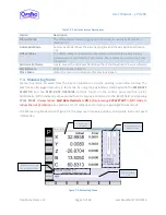
Page 27: ...he following pages The top left corner of the screen shows the P which indicates this machine is a polisher Double tapping on the P will bring up a sub menu as seen in Figure 7 10 Figure 7 1 Screen La...

Page 28: ...60 Last Modified 7 30 2014 7 2 Jump To The JUMP TO button from any screen allows quick navigation to Job Setup True Tool and Polish Setup menus Figure 7 2 JUMP TO buttons activated for quick navigatio...

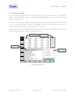
Page 29: ...eturns to the previous screen 7 4 Manual Jog Mode Manual Jog mode accessed from the P Series submenu is also the opening screen after startup The machine can be jogged manually in this mode by using t...

Page 30: ...Mode screen Figure 7 5 will display axis position spindle speed and load information cycle time and program lines The program line highlighted in grey is currently being processed The Progress bar in...

Page 31: ...both Z Axis and C Axis fields set at zero Lens Blow Off Settings These settings are used to release the lens from the polisher by pulsing the center feed slurry at a controlled pressure for a controll...

Page 32: ...8 consists of two modes In User Mode the screen is blank Entering Setup Mode requires a password which is provided to a supervisor during training This mode is not recommended for untrained personnel...

Page 33: ...left box The top right box displays current messages faults The left side of the display consists of the operation buttons each button will bring up sub menus which will be covered in detail througho...

Page 34: ...es software Close Menu Closes the menu and returns to the previous screen Figure 7 11 Information Screen from New Job Menu Screen 1 Note Job menus will have titles in front of the entry boxes Any titl...

Page 35: ...s with every other screen that relates to machine operation tap on any of the underlined items for a description of what the program is looking for Additionally the lower left corner of the screen pro...

Page 36: ...Factor in Figure 7 13 above are generally a safe place to start OptiPro recommends one general guideline stroke distances beyond 3 00 mm are unnecessarily large and generally won t help with figure co...

Page 37: ...The technician can also load a job change the name and tap Save Job to save a job under a different name After loading a job tapping Jump To will bring up the tabs for all the processes Figure 7 16 Co...

Page 38: ...hrough Figure 7 20 below show the different combinations and what the screens look like filled in Figure 7 17 A correction measuring the Optic with a test plate on an interferometer showing a 5 ring h...

Page 39: ...nual ePX 200 OptiPro Systems LLC Page 39 of 60 Last Modified 7 30 2014 Figure 7 19 A correction measuring the Pad with direct radius measurement Figure 7 20 A correction measuring the Pad with a spher...

Page 40: ...eck Program Upper and lower tram ball programs are installed with on every new ePX Should the tram programs become lost or deleted Table 7 4 and Table 7 5 will walk the technician through the Tram Pro...

Page 41: ...of the parameters into the Cycle Number 1 column The required parameters are listed in Table 7 5 Table 7 5 Summary of Polish Setup Screen Parameters Parameter Value Pause at Gap Height Checked This m...

Page 42: ...rols The relative flow rate is indicated by the number of green LEDs lit When the slurry flow is below the displayable range the 1st LED will flash green The last LED flashes green for a flow above th...

Page 43: ...set and tap save at the bottom of the screen 8 3 Recovering from Error Messages A slurry flow fault low air pressure unreferenced axes or Z Axis over travel may cause error messages to appear on the u...

Page 44: ...FAULT Table 8 2 Status Messages STATUS MESSAGES M 1 INITIALIZING SERVOS M 2 CLOSE FRONT DOOR TO CYCLE START MACHINE M 3 CLOSE FRONT DOOR TO REFERENCE MACHINE M 4 REFERENCE MACHINE M 5 CYCLE START TO Z...

Page 45: ...l information 9 1 2 End of Shift Remove any loose parts tools or other objects from the work area Wipe down the machine s exterior as needed Clean the Touch Screen with a clean soft COTTON CLOTH using...

Page 46: ...lace the chiller fluid with approximately 4 gallons of 30 Ethylene Glycol and 70 Distilled Water OptiPro recommends DOWTHERM SR 1 Allow the chiller to run for 2 minutes and top off as additional fluid...

Page 47: ...ith a metal adapter The adapter has 22mm flats for rotating against to unscrew the rotary union Unscrew the union with the tube attached Figure 9 1 Rear of C axis open with rotary union exposed Replac...

Page 48: ...8 4 4 In An Emergency 8 5 Machine Overview and User Controls 10 5 1 Work Area and Machine Axes 10 5 2 Operator Panel Interface 11 5 2 1 Jog Panel 11 5 2 2 Jog Pendant 13 5 2 3 Door Interlock 14 5 2 4...

Page 49: ...Emergency Stop 26 6 3 1 When to press E STOP 26 6 3 2 Returning machine to normal operation 26 7 Creating and Running Programs 27 7 1 Screen Layout 27 7 2 Jump To 28 7 3 P Series Submenu 28 7 4 Manua...

Page 50: ...lic Chuck Runouts 51 10 1 3 Starting the Tram Sequence and Checking B Zero Vertical Alignment 52 10 1 4 Spindles align X and Y Axis Alignments 54 10 1 5 Checking Tram Ball Runout 55 10 1 6 Finding Cen...

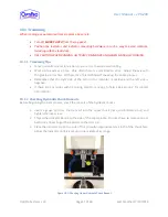
Page 51: ...d up the entire process Remember that the right side of the zero on the indicator is positive and the left side is negative If there are any issues with tramming OptiPro is happy to help See Section 2...

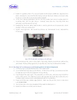
Page 52: ...Checking the Lower Hydraulic Chuck Runout 8 Check and adjust the runout of the lower chuck using only the mount bolts without the jackscrews Remove the gauge pins and indicator arm from the machine w...

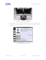
Page 53: ...igure 10 3 Indicator Position for Finding B Zero 7 Follow the directions on the screen to find the center of B When the indicator reads a movement of less than 6 m tap SET Leave the indicator on the t...

Page 54: ...icator 3 Following the directions on the screen rotate the indicator around the pin and jog the machine to correct the x and y axis errors to find the spindles aligned position Make sure to only spin...

Page 55: ...g either the jog panel see Section 5 2 1 or the machine jog wheel move the work spindle in the Y direction until the Y axis is at the positive limit of its travel closest to the operator 2 Insert the...

Page 56: ...56 of 60 Last Modified 7 30 2014 7 Follow the directions on the screen to find the center of the b axis 8 Once the indicator reads 2 m through the entire travel tap SET and move to the next screen Fi...

Page 57: ...then press CYCLE START Tap FILL MDI and press CYCLE START to go to Spindles Align 2 Follow the directions on the tram screen to find the tool length Figure 10 9 Tram Sequence Screen 4 Tool Length Pinc...

Page 58: ...chucks are close to each other as shown Figure 10 10 Finding the Chuck to Chuck Distance 2 Using a gauge block from the tram kit follow the directions on the tram screen and press SET when finished F...

Page 59: ...ce with X Y Z or B position coordinate position to move the axis to replace with desired position feed rate rate at which to move Can be over ridden by Feed Rate knob on control panel replace with des...

Page 60: ...3SF 1 Air Prep Mist Separator Bowl OptiPro 63164A SMC C3SF 1 Work Spindle Rotary Union OptiPro 69284A SMC KXL08 03S 1 Work Spindle Timing Belt OptiPro 64666A Misumi HTBN850S5M 250 0 Containment Z axis...

Reviews: