


OPTIMUM
M A S C H I N E N - G E R M A N Y
Version 1.0.1 dated 2018-01-31
Page 46
Translation of the original instructions
TM4010 | TM4010D
GB
T
M
4010_
T
M
4010D_G
B_4
.f
m
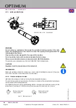
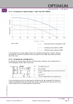
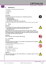
4.15.4 Turning between centres
CAUTION!
When clamping workpieces between the tips of the lathe while using a lathe dog, the
existing lathe chuck protection must be replaced with a circular lathe chuck protection.
Workpieces that require a high concentricity precision are machined between the centres. For
holding purposes, a centre hole is drilled into both plain machined faces of the workpiece.
Img.4-11: Graphic: Turning between centres
The lathe dog is clamped onto the workpiece. The driving bolt, which is screwed into the flange
for the lathe chuck, transmits the torque to the lathe dog.
The fixed centre glides into the centre hole of the workpiece on the spindle nose side. The fol-
low centre glides into the centre hole of the workpiece at the tailstock side.
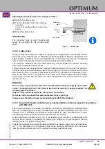
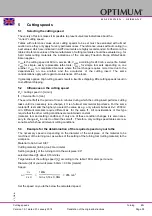
4.15.5 Turning short tapers with the top slide
Short tapers are turned manually with the top
slide. Swivel the top slide to the required
angle. The infeed is achieved with the cross
slide.
Loosen the two clamping screws in the
front and in the rear of the top slide.
Swivel the top slide.
The required setting of the angular
degree may be read from the scale.
Clamp the top slide again.
Img.4-12: Graphic: Turning tapers
Lathe dog
Chuck flange
Driving bolt
Workpiece
Follow
Centering
point
60
0
Feed
Fixed
Centre 60
0
Workpiece
Feed
Inf
eed


