Optimanufacturing T60-1001-C8-1A Operation & Service Manual Download Page 1

SOP-TN-002 Rev. Q 
T60 Operations and Service Manual 


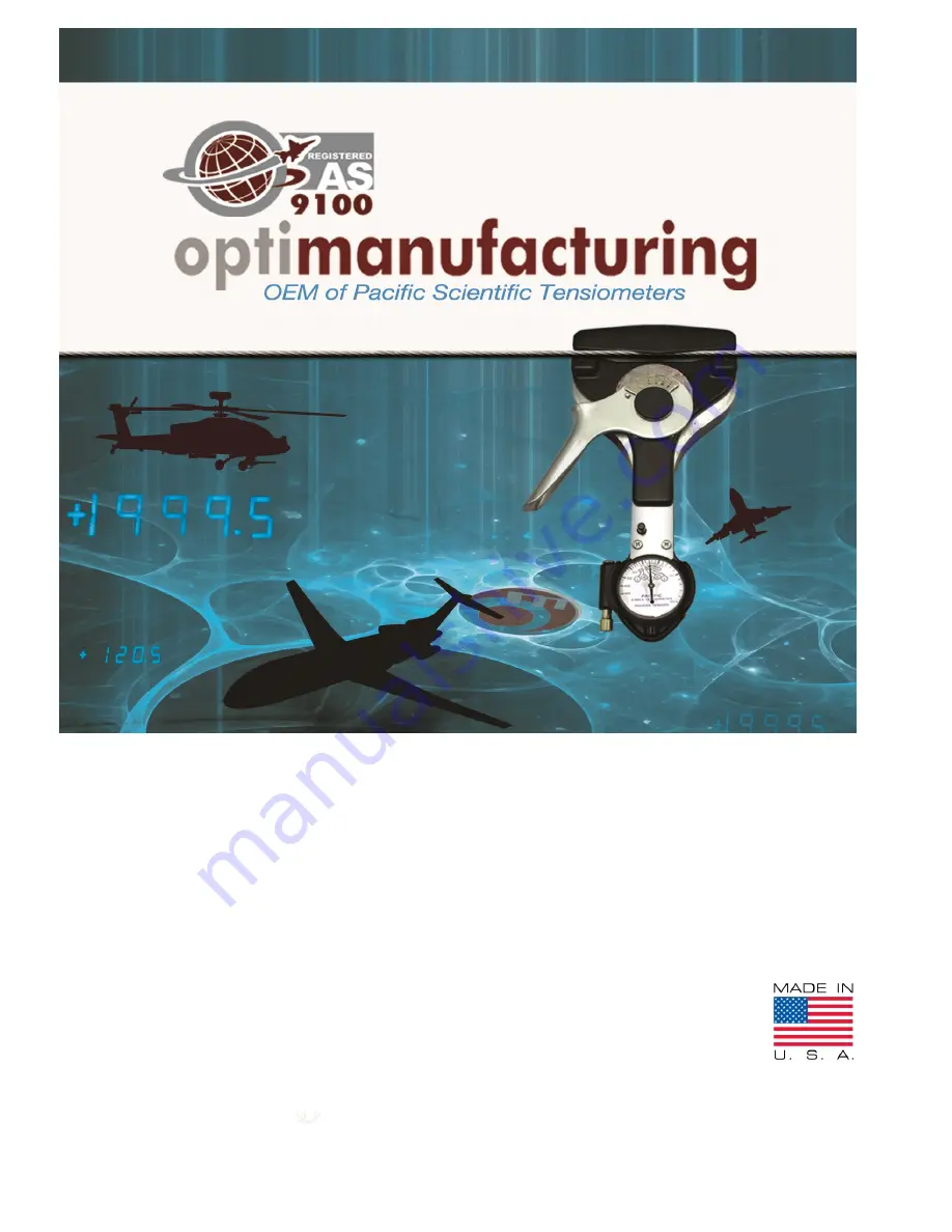
OPERATION & SERVICE MANUAL FOR  

CABLE TENSIOMETER 


T60


SERIES


PART NUMBERS: 

T60-1001-C8-1A (NSN: 6635-00-530-1128) 
T60-1001-C9-1A (NSN: 6635-00-530-1129)


T60-1002-C8-00 (BRITISH MODEL FOR CWT CABLES) 
T60-1002-C9-00 (BRITISH MODEL FOR CWT CABLES)


Summary of Contents for T60-1001-C8-1A

Page 1: ...vice Manual OPERATION SERVICE MANUAL FOR CABLE TENSIOMETER T60SERIES PART NUMBERS T60 1001 C8 1A NSN 6635 00 530 1128 T60 1001 C9 1A NSN 6635 00 530 1129 T60 1002 C8 00 BRITISH MODEL FOR CWT CABLES T60 1002 C9 00 BRITISH MODEL FOR CWT CABLES ...

Page 2: ...igure 3 Preset Instructions Type C8 6 4 5 TAKING TENSION READINGS TYPE C9 7 Figure 3 5 Preset Instructions Type C9 7 4 6 DIFFICULT LOCATIONS 7 4 7 ACCURACY 7 Table 2 T60 Accuracy Tolerance 7 4 8 TYPE OF CABLE 8 4 9 USE OF CALIBRATION BAR 8 Figure 4 Calibration Bar Instruction 8 4 10 OVERLOAD 8 SECTION V 9 PERIODIC INSPECTION MAINTENANCE AND LUBRICATION 9 5 1 GENERAL 9 Table 3 Lubrication Chart 9 S...

Page 3: ...handle head The T60 is a durable precision instrument and is not damaged by use on cable tensions beyond its range The cable Tensiometer is a hand held instrument A jaw is located at the top of instrument Actual contact on the cable is made by the riser block and the two sectors located in the jaw A sliding yoke slides up the frame of the instrument to provide a measuring force A dial indicator is...

Page 4: ...ll be use the Wrist Band adjustable see figure 1 1 Each time the cable Tensiometer is used it shall be removed from the case and the serial number stamped on the nameplate checked against the serial number on the tab of the calibration bar 3 2 PERFORMANCE The Tensiometer shall be capable for use under extreme conditions of heat or cold without affecting the accuracy of readings the operating tempe...

Page 5: ...ion will vary from the nominal depending on the errors in the instrument itself manufacturing tolerance of springs in the regulators rate of the regulator spring and condition of the control cable Cable tension readings taken on a regulated control system therefore can be misleading and can result in damage through improper rigging UP DOWN BOTTOM RIGHT TOP LEFT CALIBRATION BAR RISER CABLE GAGE POI...

Page 6: ...dle latch The latch end will be retained in the detent socket provided in the actuating handle Note When operating the instrument handle the handle should never be allowed to snap open it should be released gradually allowing the unit to clamp firmly on the cable 4 3 MEASURING CABLE DIAMETERS Figure 2 T60 Cable Diameters a With the actuating handle in the latched position move the cable size gage ...

Page 7: ... measurement you may use the instrument s integrated cable size gauge and procedure sec 4 3 b Release the handle latch by squeezing the actuating handle Retain the actuating handle unlatched against the side of the Tensiometer Place the instrument on the cable making certain that the cable is squarely aligned in the jaws and against the jaw base Slowly release the actuating handle allowing the sec...

Page 8: ...dings with the pointer lock button pressed down If the pointer lock button is depressed during a tension reading a false reading will result due to the friction of the brake mechanism 4 7 ACCURACY Because of the uneven surface of stranded cable slight variations in reading may occur on the same cable at the same tension This is especially true of 5 32 inch diameter cable and larger To obtain the g...

Page 9: ...of cables on which the Tensiometer instrument will be used 4 9 USE OF CALIBRATION BAR A Calibration bar is supplied with each Tensiometer This provides an immediate means of checking the accuracy of the instrument while in use The calibration bar has been carefully checked to read the load marked on the identification tab The identification tab also carries the serial number of the instrument for ...

Page 10: ...damaged or broken disassemble the instrument in the order of the index numbers indicated on the exploded view Figure 6 All detail parts of the instrument are so integrated that in order to perform a disassembly operation it is necessary that disassembly be started with index number 1 and continued in numerical sequence The only exception to this is the latch mechanism 37 through 40 Figure 6 Reasse...

Page 11: ... block should not deflect the mainspring 7 If it does select a riser block with a low tolerance g Place clips 4 on the lower pins of frame 41 Between the pins and the top of the clip place a 0 010 inch shim 3 on each side of the instrument h Drop spring 10 onto shaft 13 and secure with screw 9 i Check for a symmetrical bite On a pre loaded 7 32 cable start to take a tension reading but do not remo...

Page 12: ...the same cable at the same tension If closest possible accuracy is desired take three or five reading at slightly different locations on the test area of the cable and average them It is considered a unit to be out of calibration when the average reading is more than 5 of indicator or one minor division whichever is greater 7 4 INDICATOR CABLE SIZE To re establish the accuracy of the indicator cab...

Page 13: ... INSTRUCTIONS 15 16 17 18 19 20 42 22 21 23 25 24 29 18 26 27 28 35 37 38 39 30 44 36 34 33 32 45 41 40 31 12 11 18 5 3 8 7 6 2 43 46 4 9 10 13 14 1 OPERATING AND SERVICE MANUAL 47 48 SECTION VIII GROUP ASSEMBLY PARTS LIST Figure 6 Cable Tensiometer Type C8 and C9 ...

Page 14: ...djusting 1 10 T541 SPRING Follower riser 1 11 COML 0901100 48 SCREW 4 40 x 3 16 inch long hexagonal socket head cup point black oxide 2 12 T60031 POST Shaft 1 13 T60026 SHAFT Indicator 1 14 COML 0901100 99 SCREW 10 32 x 5 16 inch long socket head 1 15 T60018 PIN Center 1 16 T60022 INDICATOR Cable size 1 A B T60058 INDICATOR Cable size British Model 1 C D 17 T60019 WASHER Center pin 1 18 T60068 WAS...

Page 15: ...ong 1 43 T5138 60 CARRYING CASE ASSY 1 0922100 88 BLACK CASE 1 T5185 51 INSERT CUSHION 2 T5184 01 CUSHION T60 1 44 WI CU 002 INSTRUCTIONS SHEET Operating 1 A B WI CU 003 INSTRUCTIONS SHEET British Model 1 C D 45 T60039 LABEL INSTRUCTIONS 1 46 T60040 LABEL NAMEPLATE 1 47 SOP TN 002 OPERATION AND SERVICE MANUAL 1 ALL 48 T60007 WRIST BAND 1 ALL PART NUMBER Denotes non subassembly or final component p...

Page 16: ... 7 p 12 Add red note p 6 10 add TABLE 6 p 10 DCN 11 090 M N 4 13 2012 Correct Sec 4 8 Type of Cable Correct address add Point of Contact add sec IX Dimension and Weight DCN 12 048 N O 8 10 2012 On Sec 4 4 add note of OD when use cable coated type p 5 Correct quantity used on item 18 T60068 before 2 now 3 and correct P N on item 34 before AN960 3 now AN960 3L of Table 6 P12 13 DCN 12 071 O P 10 18 ...

Reviews: