FiberPoint MEM Installation
3-7
Form 361015-0001A
FiberPoint Structured Wiring Enclosure Installation Guide
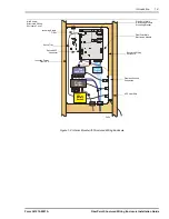
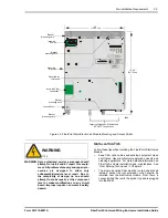
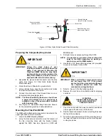
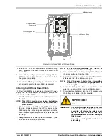
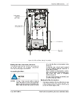
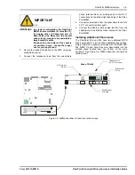
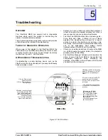
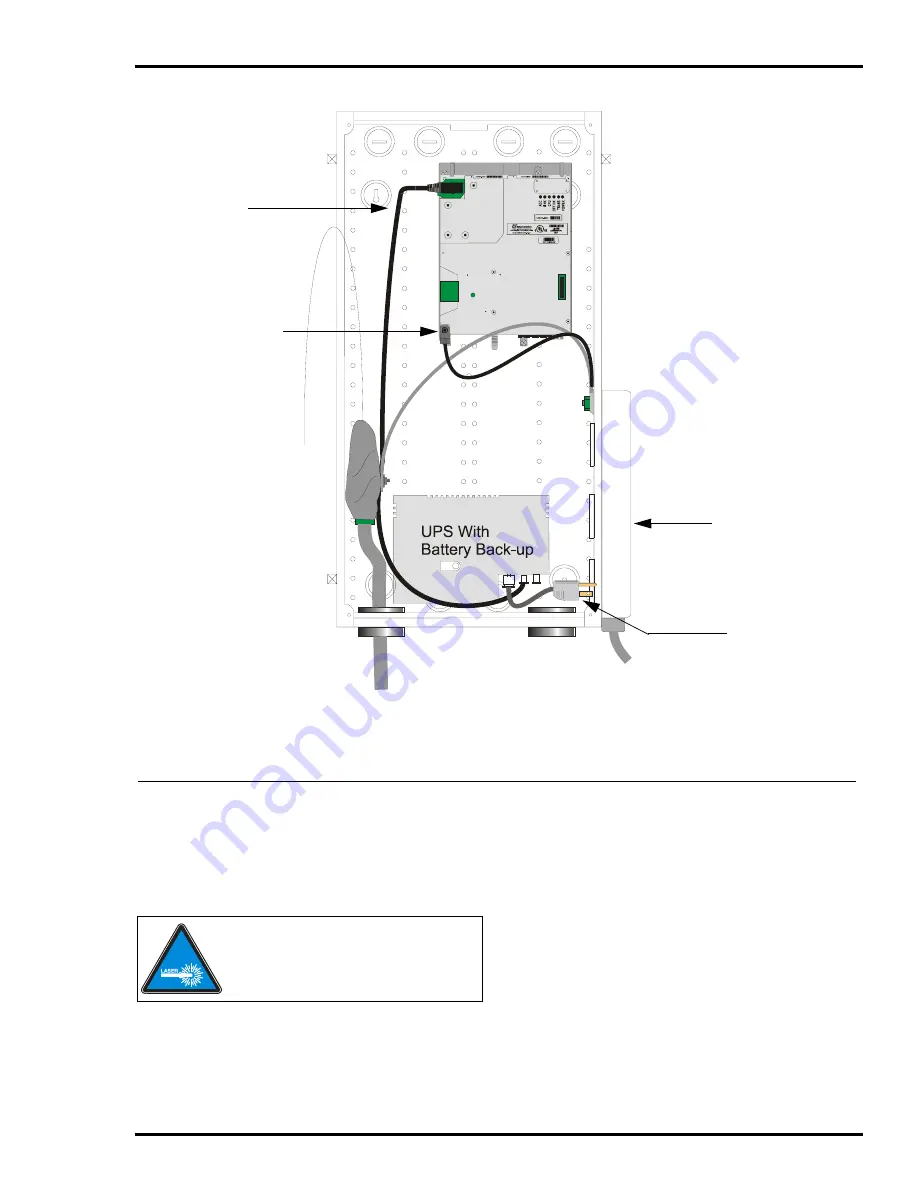
Figure 3-6: UPS and Power Supply Connections
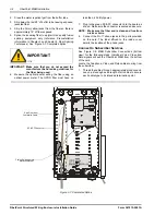
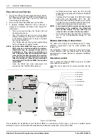
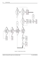
Making the Fiber Connection Overview
The single incoming fiber from the PON will be spliced to
the SC/APC connector. The pre-spliced, connectorized
fiber output will be plugged into the MEM.
Connecting the Fiber
2031
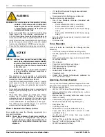
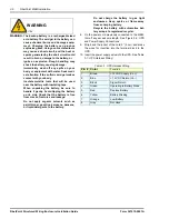
NOTICE
NOTICE: A Class 1 laser product with an internal
Class IIIb hazard is used in this equipment.
Use an optical power meter to identify active
fibers. Never assume laser power is turned
off or that the fiber is disconnected at the
other end.
A protective cap or hood must be placed
over any radiating bulkhead receptacle or
optical fiber connector.
Use of controls or adjustments or perfor-
mance of procedures other than those spec-
ified herein may result in hazardous
radiation exposure.
The use of optic instruments with this prod-
uct will increase eye hazard.
Making the Fiber Connection
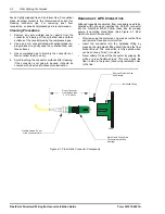
1.
Strip approximately 86” (218 cm) of fiber from the drop
cable, leaving the buffer tube intact but exposed. This
will allow sufficient length to make two complete loops
around the Fiber Management Tab.
Ground Lug and Nut
securing this corner
FiberPoint MEM
Power Cord
(trimmed to
proper length)
AC Power Strip
Plug in UPS
Power Cord
3481

