2-4
Pre-Installation Requirements
FiberPoint Structured Wiring Enclosure Installation Guide
Form 361015-0001A
WARNING
1106
WARNING: This device does not incorporate a primary
protector. If off premises coax or telephone
cable lengths exceed 140 feet (42.7 meters)
a listed primary protector is required per
the National Electric Code.
•
When routing optic fibers, be careful to avoid bending
fibers beyond the manufacturer recommended 1”
(2.54 cm) bend radius. Exceeding the bend radius can
cause excess attenuation and possibly break the fiber.
•
Verify all optical power levels before connections are
made. If excessive loss is noted, the use of an optical
time domain reflectometer (OTDR) may be required.
•
Clean the fiber ends before making any connections.
2031
NOTICE
NOTICE: A Class I laser product is used in this equip-
ment. Use an optical power meter to identify
any active fiber. Never assume laser power
is turned off or that the fiber is disconnected
at the other end.
A protective cap or hood must be placed
over any radiating bulkhead receptacle or
optical fiber connector.
•
The electronics can be sensitive to electrostatic
discharge. Use of a static wrist strap is required when
handling the FiberPoint Electronics Module.
•
The FiberPoint Electronics Module relies on a quality
earth ground in order to process signals properly.
Make sure you follow all applicable local codes for
grounding.
•
For subscribers using data services, remember that all
data wiring done internally to the home is true CAT5 in
design.
•
Fiber Optic Drop Cables (or simply drop cables)
entering the FiberPoint Electronics Module from
underground must be protected. We recommend the
use of a riser tube for protecting the drop cable. Refer
to Form 360029-0001 for specifications on riser pipe.
•
The UPS must be installed indoors in a protected
environment that has adequate airflow.
W
HAT
’
S
N
EEDED
FOR
I
NSTALLATION
Every installation needs the following components for a
successful installation:
NOTE: Check the contents of each box carefully as
you receive it. Components may not be
located where you might expect them due to
certain items being tested immediately before
shipment.
•
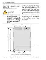
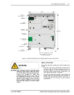
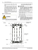
(1) FiberPoint Structured Wiring Enclosure Bracket
•
Ground Terminal
•
Nut and washer for attaching ground terminal
The above items are pre-assembled
•
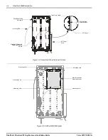
One of four Electronics Modules (consistent with
model ordered):
•
Part number MOD-FP-502 (2 Line POTS)
•
Part number MOD-FP-504 (4 Line POTS)
•
Part number MOD-FP-522 (2 POTS plus analog
video)
•
Part number MOD-FP-524 (4 POTS plus analog
video)
•
All-in-One Local power supply converter module and
Back-up UPS
•
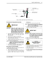
DC Power Cord
T
OOLS
R
EQUIRED
In order to install the FiberPoint, the following tools are
necessary:
•
1/8” Drill (for drilling the bracket mounting holes).
•
Drill Bits appropriate for wall anchors or fasteners of
choice.
•
7/16” nut driver for securing ground strap and MOD-
FP-502/504/522/524.
•
Wire strippers.
•
Coaxial connector stripper and crimper.
•
Flat head screwdriver (ground lug).
•
Fiber Splicing Tools.
•
Fusion Splicer for fiber optic cable.
•
Carpenter’s level.
•
Optical Time Domain Reflectometer calibrated for
1310 and 1550nm output.
A
DDITIONAL
S
UPPLIES
N
EEDED
You may need the following additional supplies. See inside
front cover of this manual for contact information on any of
the following specialty items.
•
(4) # 6 x 1/2” Pan Head Thread Cutting Screws
•
Silicone sealant (for sealing entry/exit points - outdoor
applications only).
•
Electrical tape (for sealing buffer tube ends or wires
that are not used).
•
Cotton swabs (for applying silicone sealant).
•
Assorted tie wraps (for securing cabling, etc.)
•
Fiber Splice Tray
•
Tip & Ring Connectors
•
Additional RJ-11 Jumpers (MOD-FP-504, 524)
•
F-type coax cable (from CATV out port to inside
subscribers home).
•
(1) 60” p/n 12-219 Hi-cap riser pipe (outdoor
applications only).
•
TexWipe™ Alco pad for fiber cleaning (TX806).
•
Texwipe™ cloth for fiber cleaning (TX304).
•
SC/APC connectors (for fiber).

