


- 26 -
optek-Manual--1004-1010-02--ProfibusPA-US-2017-06-23
Specifications
7
Specifications
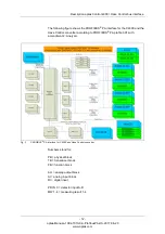
The PROFIBUS
®
PA interface for C4000 and Haze Control converters supports
PROFIBUS
®
PA profile version 3.01 with amendment 2 Analyzer. The following
blocks are used:
Note!
A detailed description of the bus interface is given in "Description optek Control
4000 / Haze Control bus interface", chapter 5, page 10.
An unambiguous slot number is assigned to each block. Within a block, all
parameters are assigned with an index in ascending order which allows
unequivocal assignment.
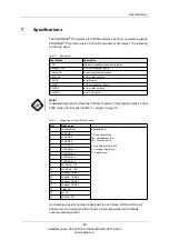
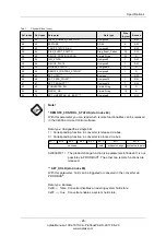
Tab. 5
Device info
User blocks
Description
1 PB
with device-specific expansion features
4 analyzer TBs
for four measuring results
1 status TB
for device status information
1 relay TB
for four relay outputs
1 AO TB
for mA inputs
4 AI FBs
for four measuring results
4 DI FBs
for four relay outputs
2 AO FBs
for two mA-inputs
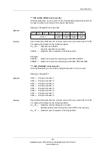
Tab. 6
Assignment of the different blocks
Slot
Block name
0
Physical Block
Abbreviations:
PB = physical block
TB = transducer block
FB = function block
AO = analog output block
AI = analog input block
DI = digital input
1
AI FB M01
2
AI FB M02
3
AI FB M03
4
AI FB M04
5
DI FB Relay 1
6
DI FB Relay 2
7
DI FB Relay 3
8
DI FB Relay 4
9
AO FB mA_IN1
10
AO FB mA_IN2
11
Analyzer TB M01
12
Analyzer TB M02
13
Analyzer TB M03
14
Analyzer TB M04
15
Relay TB
16
AO TB
17
STATUS_TB