


Description optek Control 4000 / Haze Control bus interface
- 17 -
optek-Manual--1004-1010-02--ProfibusPA-US-2017-06-23
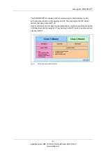
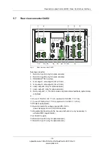
5.5
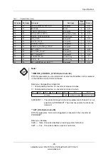
Rear view converter C4252
Fig. 7
Rear view converter C4252
Numbers stand for:
1. Detector input A (only for optek-sensors)
2. -
3. PROFIBUS
®
PA interface
4. mA-output 1, mA-output 2 (0/4–20 mA)
5. mA-output 3, mA-output 4 (0/4–20 mA)
6. Lamp output E (only for optek-sensors)
7. Lamp output F (only for optek-sensors)
8. Relay outputs 1, 2, 3 for limit values or system status feedback, system relay
(enabled)
9. -
10. Fuse I 115/230 V AC T 1.6 A (option 24 V AC/DC: T 3.15 A)
11. Fuse II 115/230 V AC T 1.6 A (option 24 V AC/DC: T 3.15 A)
12. Power supply (fixed)
13. Selector switch for voltage (preset 230 V AC) -
(does not apply for a 24 V AC/DC version)
14. Equipotential bonding (in the non-ex-proof version, only necessary in
extreme EMC requirements)
15. ON / OFF switch
16. -
17. Detector input C (only for optek-sensors)
21
20
19
DETECTOR INPUTS
DETECTOR INPUTS
[C]
5
4
3
[A]
1
5
2
5
4
3
[D]
[B]
1
5
2
OPTEK - DANULAT
115 / 230 V, 50 / 60 Hz, 50 VA
PA
M6
N
PE
L
115 / 230 V, T 1,6 A
230V
!
0 / 4 - 20 mA
MADE IN GERMANY
17
16
18
10
12
11
15
14
13
OUT 1, 2
24 V AC / DC
RELAY OUT
41
43
42
40
6
V DC
7
6
7
LAMP [F]
7
7
6
V DC
acc. to
cable
length
acc. to
length
cable
44
45
47
46
LAMP [E]
6
OUT 3, 4
R6
R8
RR
R7
R2
R5
R4
R3
R1
36
39
37
38
32
34
35
33
31
REMOTE IN
24 V DC
51
53
54
52
1
4
6
8
10
11
12
13
14
15
17
3
7
5