


Description PROFIBUS
®
- 8 -
optek-Manual--1004-1010-02--ProfibusPA-US-2017-06-23
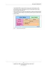
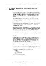
The figure below shows the principle structure of a PROFIBUS
®
system. All
devices are connected in a bus structure (line). Up to 32 stations can be
interconnected in one segment. At the beginning and end, each PROFIBUS
®
segment must be terminated.
Fig. 1
Principle structure of a PROFIBUS
®
system
A DP/PA segment coupler or a DP/PA link allows the connection of
PROFIBUS
®
DP and PROFIBUS
®
PA. A PROFIBUS
®
PA segment is always a
subsegment of a DP segment.
DP/PA segment
coupler
A DP/PA segment coupler is a signal converter which adjusts RS485 signals to
the MBP signal level and vice versa. It does not have an individual bus address
and is transparent for the DP master stations. Therefore, only certain bit rates
are possible in the DP segment (e. g. 45.45 kbit/s).
DP/PA link
The DP/PA link has a slave station address over which the DP master accesses
the PA segment. In the DP segment, an independent bit rate of 12 Mbit/s
maximum is possible.