background image


OPT MACHINE VISION TECH.CO. LTD


ADD:8 JingSheng Road, JingXia ChangAn DongGuan China 523853 

                                                                                                                    TEL: 0769-82716188                        FAX: 0769-81606698   

                                                                                                                    E-mail:

[email protected]

              Website:Http://www.optmv.net


13 

3.3 Setting intensity   

      1

manually setting: Turn both the switch 1 and switch 2 on the front panel to “ON” position to enter the general lighting 

mode. Push the encoder. The first digit of the LED will blink. Now one can choose the channel(s). Clock-wise turning the 

encoder will increase the index of the channel whereas counter clock-wise turning will decrease the index.    The remaining 

digits indicate the intensity level (0-255) in decimal form (i.e., for the highest intensity, set the 2

nd

 digit= 2, the 3rd digit= 5, 

the  4

th

  digit=5).  Push  the  encoder  again  to  store  the  value  and  the  LED  will  stop  blinking.  Repeat  above  steps  for  the 

remaining channels.   

      2

setting via software: See Sect.4 - “software operation instruction” 

3.4 External trigger 

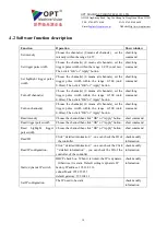
  There are 4 trigger interfaces. COM is the common external trigger negative input signal and TRIG 1

2

3

4 is the 

external trigger positive input. Optocoupler isolation is built in. For voltage 0-4V, the optocoupler isolation is not conductive 

and it becomes conductive when the voltage is within 7 -24V. For default, it is positive edge triggered. 


The controller can enter general/highlight trigger mode by turning the working mode switches accordingly (For general 

trigger mode switch 1 “OFF”, switch 2 “ON” while for highlight trigger mode, both switch 1 and switch 2 are “OFF”). The 

trigger delay (1-999ms for general trigger mode/ 0.01-5.00ms for highlight trigger mode) can be adjusted through encoder or 

software. A decimal point will appear under highlight trigger mode where maximum value will not exceed 5.00. 


Summary of Contents for OPT-DPA1024E-4

Page 1: ...JingSheng Road JingXia ChangAn DongGuan China 523853 TEL 0769 82716188 FAX 0769 81606698 E mail optmv1 optmv com Website Http www optmv net 1 OPT DPA1024E 4 LED lighting controller manual OPT MACHINE VISION TECH CO LTD Revised in Dec 2014 ...

Page 2: ...or notice Caution and warning Caution and Warning This product should be connected to 220V AC power supply Please ensure that the power switch controller is off when plugging in out the power to prevent against electric shock Please read the manual carefully in advance and strictly follow the instructions when operating the product In case of any abnormal situation please contact us and never disa...

Page 3: ...current 8 1 5 2 General Highlight trigger mode 8 1 5 3 Error code 8 1 5 4 Working mode switch 9 2 Installation Guidance 10 2 1 DIN guide rail installation 11 2 2 Screw installation 11 2 3 Installation size 11 3 Operation Instructions 12 3 1 Wiring diagram 12 3 2 Turn on light source 12 3 3 Setting intensity 13 3 4 External trigger 13 4 Software Operation Instructions 14 4 1 Software interface desc...

Page 4: ...8 Turning off channel s 30 2 9 Turning off multiple channels 31 2 10 Setting intensity 31 2 11 Setting multiple intensity 32 2 12 Reading intensity 32 2 13 Setting the trigger pulse width 33 2 14 Setting multiple trigger pulse width 33 2 15 Reading the trigger pulse width 34 2 16 Setting high brightness trigger pulse width 34 2 17 Setting multiple high brightness trigger pulse width 35 2 18 Reading ...

Page 5: ...lly checks for light source maximum current hot swapping light source manually setting the maximum output current 100M Ethernet communication RS232 communication 1 2 Selection guidance 1 2 1 Accessory selection guidance 1 Network cable Factory standard network cable CAT6 or later 3m length Cable requirement CAT6 or later no longer than 50m 2 Router or switch Choose well known brands The transmissi...

Page 6: ...h error message ER2 from LED Overcurrent protection Enabled If overcurrent occurs the overcurrent protection will turn off the corresponding channel with error message ER1 from LED General trigger mode Intensity level 0 255 adjustable See Sect 1 5 6 Highlight trigger mode The current is 1A for single channel See Sect 1 5 6 General trigger delay 1 999ms Configurable by front panel encoder or softwa...

Page 7: ...on Remark 1 4 digit LED From left to right the 1st digit equals the channel index and the remaining three digits are decimal representation of the corresponding channel parameter See Sect 3 3 3 4 2 Working mode switch Switch working mode see Sect 1 5 6 3 Serial port For communication with PC via RS232 4 100M Ethernet port For communication with PC via Ethernet 6 encoder 2 working mode switches 8 t...

Page 8: ... 1 5 2 General Highlight trigger mode The controller can enter the two modes by turning the working mode switches accordingly For general trigger mode switch 1 OFF switch 2 ON while for highlight trigger mode both switch 1 and switch 2 are OFF Set the trigger delay through adjusting the encoder or software The range of the adjustable intensity is 0 255 Optocoupler isolation is built in For voltage...

Page 9: ...e OFF ON Highlight trigger mode OFF OFF Note 1 DPA1024E 4 controller can only connect 24V light source 2 The maximum current is 1A for single channel and 2 2A for 4 channels 3 When manually setting the maximum output current never connect the controller to the light source with current lower than the maximum output current Otherwise it may damage the light source because of current mismatch 4 Auto...

Page 10: ...Xia ChangAn DongGuan China 523853 TEL 0769 82716188 FAX 0769 81606698 E mail optmv1 optmv com Website Http www optmv net 10 2 Installation Guidance Index Interface Description Remark 1 Screw hole Install screw 2 DIN rail track Standard DIN rail installation ...

Page 11: ...ack to position 1 rail 2 Push down controller toward position 2 2 Uninstallation Fig 2 2 1 Pull down the controller 2 Push up toward position1 2 2 Screw installation Installation Fig 2 3 1 Secure back plate against controller 2 Tighten the screws 3 Tighten the back plate to fixtures or stations 2 3 Installation size Fig 2 2 Guide rail Uninstallation Fig 2 4 DIN guide rail size Fig 2 3 Screws insta...

Page 12: ...ty through software please connect the controller with power off to PC via RS232 or Ethernet Run our Demo program or one s own program i e SDK also available The parameters for channels can still be overridden manually via front panel while communicating through serial port or Ethernet i e both host computer and the controller can be individually adjusted There is no need to switch the working mod...

Page 13: ...LED will stop blinking Repeat above steps for the remaining channels 2 setting via software See Sect 4 software operation instruction 3 4 External trigger There are 4 trigger interfaces COM is the common external trigger negative input signal and TRIG 1 2 3 4 is the external trigger positive input Optocoupler isolation is built in For voltage 0 4V the optocoupler isolation is not conductive and it...

Page 14: ... of the controller of the controller 3 Dis connection After choosing the proper device click connect to establish communication or disconnect to destroy the communication 4 Search device Searching available devices 5 Verify modify information Click Detailed information one can verify or modify the detailed communication parameters For serial port communication one can verify serial port number and...

Page 15: ...the corresponding channel can be adjusted by moving the slider 11 intensity value Type in the intensity value to be set 12 channel switch Turn on off the corresponding channel 13 language Switch language between Chinese and English Fig 4 2 Short command communication window Index Interface Description Remark 1 choose function choose function 2 choose channel choose channel s for operation 3 parame...

Page 16: ...optmv com Website Http www optmv net 16 Fig 4 3 Long command communication window Index Interface Description Remark 1 Choose function Choose function 2 Choose channel Tick the box to choose the channel for operation 3 OK button Send data then quit 4 Cancel button Quit 5 Apply button Send data 1 3 OK button 5 Apply button 2 4 Cancel button ...

Page 17: ...www optmv net 17 Fig 4 3 Multi channel window Index Interface Description Remark 1 Intensity setting slider The intensity for each channel can be adjusted by moving the slider 2 Intensity value choose the channel and type in the intensity value 3 Channel switch Turn on off the corresponding channel 1 slider for adjust intensity 2 intensity value 3 channel switch ...

Page 18: ... OK or Apply button short long command Turn on channel s Choose the channel s 0 means all channels set the trigger pulse width within the range 0 500 unit 0 01ms Then click OK or Apply button short long command Read intensity Choose the channel then click OK or Apply button short command Read trigger pulse width Choose the channel then click OK or Apply button short command Read highlight trigger ...

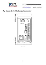
Page 19: ... VISION TECH CO LTD ADD 8 JingSheng Road JingXia ChangAn DongGuan China 523853 TEL 0769 82716188 FAX 0769 81606698 E mail optmv1 optmv com Website Http www optmv net 19 5 Appendix A Mechanical parameter Front view ...

Page 20: ...OPT MACHINE VISION TECH CO LTD ADD 8 JingSheng Road JingXia ChangAn DongGuan China 523853 TEL 0769 82716188 FAX 0769 81606698 E mail optmv1 optmv com Website Http www optmv net 20 Left view ...

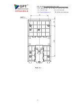
Page 21: ...OPT MACHINE VISION TECH CO LTD ADD 8 JingSheng Road JingXia ChangAn DongGuan China 523853 TEL 0769 82716188 FAX 0769 81606698 E mail optmv1 optmv com Website Http www optmv net 21 Back view ...

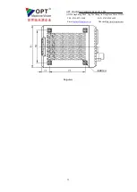
Page 22: ...OPT MACHINE VISION TECH CO LTD ADD 8 JingSheng Road JingXia ChangAn DongGuan China 523853 TEL 0769 82716188 FAX 0769 81606698 E mail optmv1 optmv com Website Http www optmv net 22 Top view ...

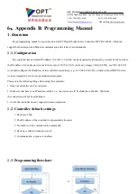
Page 23: ...orm of 192 168 1 X X can be any integer within 0 255 say 192 168 24 X we should configure the IP address of the controller accordingly e g 192 168 24 X1 For a switch without DHCP Server we have integrated a tool in our demonstration program Please note the following things when using the controller 1 Only one controller can be connected 2 Make sure that here is no IP address conflict i e one device...

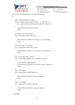
Page 24: ...s communication Here we simply take setting the intensity for example respectively All the steps within dashed rectangle which are achieved with function codes are replaceable 1 4 Example programs We recommend 20ms time interval between a pair of Set and Read operations offering room for the controller to react 1 4 1 An example in C using System using System Collections Generic using System Linq u...

Page 25: ... OptController SetIntensity 0 0 Console WriteLine Failed to set intensity 0 for all channels break Set the intensity 255 to channel 1 if 0 OptController SetIntensity 0 255 Console WriteLine Failed to set intensity 255 for all channels break Read the intensity of the 1st chanel if 0 OptController ReadIntensity 1 ref IntensityValue Console WriteLine IntensityValue Console WriteLine Failed to read in...

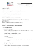
Page 26: ...ller_InitSerialPort W2A strCOMName GetBuffer 0 m_OPTControllerHandle OPTController_CreateEtheConnectionBySN W2A strSNe GetBuffer 0 m_OPTControllerHandle OPTController_DestoryEtheConnection m_OPTControllerHandle Turn on the 1st channel OPTController_TurnOnChannel m_OPTControllerHanlde 1 Turn off the 1st channel OPTController_TurnOffChannel m_OPTControllerHanlde 1 Set the intensity 255 to the 3rd ch...

Page 27: ...ore you read the intensity you need to delay Dim nIntensity As Integer Threading Thread Sleep 100 OPTControllerAPI OPTController_ReadIntensity controllerHandle 1 nIntensity Disconnect the controller OPTControllerAPI OPTController_DestoryEtheConnection controllerHandle 2 Function Specification 2 1 Initializing a serial port 1 Function long OPTController InitSerialPort char comName OPTController HAND...

Page 28: ...dress 3 Input s char serverIPAddress the IP of the server e g IP address of the device which is employed as server The server IP address can be 127 0 0 1 4 Output s controllerHandle the handle of the controller 5 Return value succeed OPT SUCCEED failed OPT ERR CREATEETHECON FAILED see the error code in Tab 1 6 Remarks connect to a server as a client Before connecting make sure that the controller ...

Page 29: ... destroying an Ethernet connection 2 5 Destroying an Ethernet connection 1 Function long OPTController DestroyEtheConnection OPTController HANDLE controllerHandle 2 Description disconnect an existing Ethernet Connection 3 Input s controllerHandle the handle of the controller 4 Return value succeed OPT SUCCEED failed OPT ERR DESTORYETHECON FAILED see the error code in Tab 1 5 See also creating an E...

Page 30: ...trollerHandle the handle of controller channelIndexArray an array consists of the indexes of the channels to be turned on range 1 16 in decimal form length the length of the channel index array 4 Return value succeed OPT SUCCEED failed OPT ERR TURNONCH FAILED or OPT ERR CHINDEX OUTRANGE see the error code in Tab 1 5 See also turning off multiple channels 2 8 Turning off channel s 1 Function long OPT...

Page 31: ...ontroller channelIndexArray an array consists of the indexes of the channels to be turned off range 1 16 in decimal form length the length of the channel index array 4 Return value succeed OPT SUCCEED failed OPT ERR TURNOFFCH FAILED or OPT ERR CHINDEX OUTRANGE see the error code in Tab 1 5 See also turning on multiple channels 2 10 Setting intensity 1 Function long OPTController SetIntensity OPTCon...

Page 32: ...ontrollerHandle the handle of controller intensityArray an array consists of the intensities and the indexes of the corresponding channels to be set range 0 255 in decimal form length the length of the intensity array 4 Return value succeed OPT SUCCEED failed OPT ERR SET INTENSITY FAILED or OPT ERR PARAM OUTRANGE see the error code Tab 1 5 See also reading intensity 2 12 Reading intensity 1 Functi...

Page 33: ...el s range 0 16 in decimal form 0 for all channels triggerWidth the value of the trigger pulse width to be set range 1 999 4 Return value succeed OPT SUCCEED failed OPT ERR SET TRIGGERWIDTH FAILED OPT ERR CHINDEX OUTRANGE or OPT ERR PARAM OUTRANGE see the error code in Tab 1 5 See also reading the trigger pulse width 2 14 Setting multiple trigger pulse width 1 Function long OPTController SetTrigge...

Page 34: ...dex the index of the channel range 1 16 in decimal form 4 Output s triggerWidth the obtained trigger pulse width 5 Return value succeed OPT SUCCEED failed OPT ERR READ TRIGGERWIDTH FAILED or OPT ERR CHINDEX OUTRANGE see the error code in Tab 1 6 See also setting the trigger pulse width and setting multiple trigger pulse width 2 16 Setting high brightness trigger pulse width 1 Function long OPTCont...

Page 35: ...dthArray an array consists of values of the high brightness trigger pulse width and the indexes of the corresponding channels to be set range 1 500 length the length of the high brightness trigger width array 4 Return value succeed OPT SUCCEED failed OPT ERR SET HBTRIGGERWIDTH FAILED OPT ERR CHINDEX OUTRANGE or OPT ERR PARAM OUTRANGE see the error code in Tab 1 5 See also reading the high brightne...

Page 36: ...rollerHandle the handle of controller isResponse true means need return value while false stands for not 4 Return value succeed OPT SUCCEED failed OPT ERR UNKOWN see the error code in Tab 1 2 20 Enable checksum 1 Function OPTController EnableCheckSum OPTController Handle controllerHandle bool isCheckSum 2 Description to set whether checksum are needed or not 3 Input controllerHandle the handle of ...

Page 37: ...he serial number SN of the controller 3 Input s controllerHandle the handle of controller 4 Output s SN the obtained serial number 5 Return value succeed OPT SUCCEED failed OPT ERR READ SN FAILED see the error code in Tab 1 2 23 Reading IP configuration 1 Function long OPTController ReadIPConfig OPTController Handle controllerHandle char IP char subnetMask char defaultGateway 2 Description read IP c...

Page 38: ...ations are successfully done Please check whether the responses from the functions are enabled see how to enable response in Sect 2 19 A 4 Why the controller can t find any available PC serial port or serial port connection can t be established If the PC is equipped with WIN7 OS please try to run as administrator A 5 Why the controller can t be opened system errors are reported To tackle this probl...

Page 39: ...the specified channel s OPT ERR READ INTENSITY FAILED 3001012 failed to read the intensity for the specified channel OPT ERR SET TRIGGERWIDTH FAILED 3001013 failed to set trigger pulse width OPT ERR READ TRIGGERWIDTH FAILED 3001014 failed to read trigger pulse width OPT ERR SET HBTRIGGERWIDTH FAILED 3001015 failed to set high brightness trigger pulse width OPT ERR READ HBTRIGGERWIDTH FAILED 3001016 ...

Page 40: ...TD ADD 8 JingSheng Road JingXia ChangAn DongGuan China 523853 TEL 0769 82716188 FAX 0769 81606698 E mail optmv1 optmv com Website Http www optmv net 40 ETHE Ethernet HB high brightness PARAM parameter SN serial number 1 screw hole ...

Reviews: